C8051F930DK Silicon Laboratories Inc, C8051F930DK Datasheet - Page 291
C8051F930DK
Manufacturer Part Number
C8051F930DK
Description
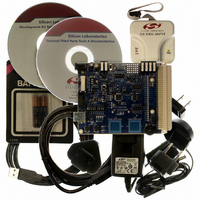
KIT DEV C8051F920,F921,F930,F931
Manufacturer
Silicon Laboratories Inc
Type
MCUr
Specifications of C8051F930DK
Contents
Target Board, Power Adapter, USB Debug Adapter, Cables, Batteries, and Software
Processor To Be Evaluated
C8051F930
Processor Series
C8051F9xx
Data Bus Width
8 bit
Interface Type
I2C, UART, SPI
Maximum Operating Temperature
+ 85 C
Minimum Operating Temperature
- 40 C
Operating Supply Voltage
0.9 V to 3.6 V
Lead Free Status / RoHS Status
Lead free / RoHS Compliant
For Use With/related Products
C8051F920, F921, F930, F931
Lead Free Status / Rohs Status
Lead free / RoHS Compliant
Other names
336-1473
Available stocks
Company
Part Number
Manufacturer
Quantity
Price
Company:

Part Number:
C8051F930DK
Manufacturer:
Silicon Labs
Quantity:
135


SFR Definition 25.8. TMR2CN: Timer 2 Control
SFR Page = 0x0; SFR Address = 0xC8; Bit-Addressable
Reset
Name
Bit
1:0
Type
7
6
5
4
3
2
Bit
T2XCLK[1:0]
TF2CEN
T2SPLIT
TF2LEN
Name
TF2H
TF2H
TF2L
TR2
R/W
7
0
Timer 2 High Byte Overflow Flag.
Set by hardware when the Timer 2 high byte overflows from 0xFF to 0x00. In 16 bit
mode, this will occur when Timer 2 overflows from 0xFFFF to 0x0000. When the
Timer 2 interrupt is enabled, setting this bit causes the CPU to vector to the
Timer 2 interrupt service routine. This bit is not automatically cleared by hardware.
Timer 2 Low Byte Overflow Flag.
Set by hardware when the Timer 2 low byte overflows from 0xFF to 0x00. TF2L will
be set when the low byte overflows regardless of the Timer 2 mode. This bit is not
automatically cleared by hardware.
Timer 2 Low Byte Interrupt Enable.
When set to 1, this bit enables Timer 2 Low Byte interrupts. If Timer 2 interrupts
are also enabled, an interrupt will be generated when the low byte of Timer 2 over-
flows.
Timer 2 Capture Enable.
When set to 1, this bit enables Timer 2 Capture Mode.
Timer 2 Split Mode Enable.
When set to 1, Timer 2 operates as two 8-bit timers with auto-reload. Otherwise,
Timer 2 operates in 16-bit auto-reload mode.
Timer 2 Run Control.
Timer 2 is enabled by setting this bit to 1. In 8-bit mode, this bit enables/disables
TMR2H only; TMR2L is always enabled in split mode.
Timer 2 External Clock Select.
This bit selects the “external” and “capture trigger” clock sources for Timer 2. If
Timer 2 is in 8-bit mode, this bit selects the “external” clock source for both timer
bytes. Timer 2 Clock Select bits (T2MH and T2ML in register CKCON) may still be
used to select between the “external” clock and the system clock for either timer.
Note: External clock sources are synchronized with the system clock.
00: External Clock is SYSCLK/12. Capture trigger is SmaRTClock/8.
01: External Clock is Comparator 0. Capture trigger is SmaRTClock/8.
10: External Clock is SYSCLK/12. Capture trigger is Comparator 0.
11: External Clock is SmaRTClock/8. Capture trigger is Comparator 0.
TF2L
R/W
0
6
TF2LEN
R/W
5
0
TF2CEN
R/W
Rev. 1.1
4
0
C8051F93x-C8051F92x
T2SPLIT
Function
R/W
3
0
TR2
R/W
2
0
1
0
T2XCLK[1:0]
R/W
0
0
291
Related parts for C8051F930DK
Image
Part Number
Description
Manufacturer
Datasheet
Request
R

Part Number:
Description:
SMD/C°/SINGLE-ENDED OUTPUT SILICON OSCILLATOR
Manufacturer:
Silicon Laboratories Inc
Part Number:
Description:
Manufacturer:
Silicon Laboratories Inc
Datasheet:
Part Number:
Description:
N/A N/A/SI4010 AES KEYFOB DEMO WITH LCD RX
Manufacturer:
Silicon Laboratories Inc
Datasheet:
Part Number:
Description:
N/A N/A/SI4010 SIMPLIFIED KEY FOB DEMO WITH LED RX
Manufacturer:
Silicon Laboratories Inc
Datasheet:
Part Number:
Description:
N/A/-40 TO 85 OC/EZLINK MODULE; F930/4432 HIGH BAND (REV E/B1)
Manufacturer:
Silicon Laboratories Inc
Part Number:
Description:
EZLink Module; F930/4432 Low Band (rev e/B1)
Manufacturer:
Silicon Laboratories Inc
Part Number:
Description:
I°/4460 10 DBM RADIO TEST CARD 434 MHZ
Manufacturer:
Silicon Laboratories Inc
Part Number:
Description:
I°/4461 14 DBM RADIO TEST CARD 868 MHZ
Manufacturer:
Silicon Laboratories Inc
Part Number:
Description:
I°/4463 20 DBM RFSWITCH RADIO TEST CARD 460 MHZ
Manufacturer:
Silicon Laboratories Inc
Part Number:
Description:
I°/4463 20 DBM RADIO TEST CARD 868 MHZ
Manufacturer:
Silicon Laboratories Inc
Part Number:
Description:
I°/4463 27 DBM RADIO TEST CARD 868 MHZ
Manufacturer:
Silicon Laboratories Inc
Part Number:
Description:
I°/4463 SKYWORKS 30 DBM RADIO TEST CARD 915 MHZ
Manufacturer:
Silicon Laboratories Inc
Part Number:
Description:
N/A N/A/-40 TO 85 OC/4463 RFMD 30 DBM RADIO TEST CARD 915 MHZ
Manufacturer:
Silicon Laboratories Inc
Part Number:
Description:
I°/4463 20 DBM RADIO TEST CARD 169 MHZ
Manufacturer:
Silicon Laboratories Inc