STM3210E-EVAL STMicroelectronics, STM3210E-EVAL Datasheet - Page 11
STM3210E-EVAL
Manufacturer Part Number
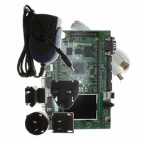
STM3210E-EVAL
Description
BOARD EVALUTION FOR STM32 512K
Manufacturer
STMicroelectronics
Type
MCUr
Specifications of STM3210E-EVAL
Contents
Evaluation Board
Processor To Be Evaluated
STM32F103Z
Data Bus Width
32 bit
Interface Type
RS-232, USB
Silicon Manufacturer
ST Micro
Core Architecture
ARM
Core Sub-architecture
Cortex - M3
Silicon Core Number
STM32
Silicon Family Name
STM32F1xx
For Use With/related Products
STM32
Lead Free Status / RoHS Status
Lead free / RoHS Compliant
Other names
497-6438
Available stocks
Company
Part Number
Manufacturer
Quantity
Price
Company:

Part Number:
STM3210E-EVAL
Manufacturer:
STMicroelectronics
Quantity:
135
Company:
Part Number:
STM3210E-EVAL
Manufacturer:
STMicroelectronics
Quantity:
1


UM0488
2.10
2.11
Smartcard
STMicroelectronics smartcard interface chip ST8024 is used on the STM3210E-EVAL board
for asynchronous 3 V and 5 V smartcards. It performs all supply protection and control
functions based on the connections with STM32F103ZGT6 listed in
The Smartcard_CMDVCC and Smartcard_OFF are multiplexed with motor control.
They can be enabled by setting the jumpers JP15 and JP16. Refer to
control on page 10
Table 7.
Table 8.
MicroSD Card
The 128 Mbyte MicroSD Card connected to SDIO of STM32F103ZGT6 is available on the
board. MicroSD Card detection is managed by standard IO port PF11.
The MicroSD Card_D3 is multiplexed with IrDA. It can be enabled by setting the jumper
JP22, as explained in
The MicroSD Card_D0 and MicroSD Card CMD are multiplexed with the motor control
connector. They can be enabled by setting the jumpers JP17 and JP20.
Table 9.
ST8024 signals
5V/3V
I/OUC
XTAL1
OFF
RSTIN
CMDVCC
JP15
JP16
JP17
JP20
Jumper
Jumper
Connection between ST8024 and STM32F103ZGT6
Smartcard related jumpers
MicroSD Card related jumpers
Smartcard power supply selection pin
MCU data I/O line
Crystal or external clock input
Detect presence of a card, interrupt to MCU, share same
pin with motor controller
Card reset input from MCU
Start activation sequence input (active low), share same
pin with I
The CMDVCC is connected to PC6 when JP15 is closed. It should be kept on
open, or the SD Card needs to be removed from the MicroSD Card connector
when PC6 is used by I
The OFF is connected to PC7 when JP16 is closed. It has to be kept on open
when PC7 is used by the motor control connector. Default setting: not fitted
JP17 is used to enable MicroSD Card data line D0. MicroSD Card D0 is enabled
when JP17 is fitted. The JP17 should be kept on open when motor control
connector CN1 is used. Default setting: fitted
JP20 is used by the motor control connector, refer to
should be kept on open for MicroSD Card operation. JTAG debugging is disabled
when JP20 is fitted.
for details.
Section 2.14: IrDA on page
2
S DAC and motor control
Doc ID 14220 Rev 5
Description
2
S or motor control connector. Default setting: not fitted
Description
Description
12.
Hardware layout and configuration
Table 6
Table
Section 2.9: Motor
for details. JP20
7.
STM32F10X
Connect to
PB10
PB12
PB11
PC7
PC6
PB0
11/48
Related parts for STM3210E-EVAL
Image
Part Number
Description
Manufacturer
Datasheet
Request
R

Part Number:
Description:
KIT STARTER FOR STM32 512K FLASH
Manufacturer:
STMicroelectronics
Datasheet:

Part Number:
Description:
KIT STARTER FOR STM32F10XE MCU
Manufacturer:
STMicroelectronics
Datasheet:

Part Number:
Description:
STARTER KIT FOR STM32
Manufacturer:
STMicroelectronics
Datasheet:

Part Number:
Description:
KIT STARTER FOR STM32F10XE MCU
Manufacturer:
STMicroelectronics
Datasheet:

Part Number:
Description:
DEV KIT FOR STM32
Manufacturer:
STMicroelectronics
Datasheet:

Part Number:
Description:
MCU ARM 128KB FLASH MEM 64-LQFP
Manufacturer:
STMicroelectronics
Datasheet:

Part Number:
Description:
MCU ARM 32BIT 128KB FLASH 64BGA
Manufacturer:
STMicroelectronics
Datasheet:

Part Number:
Description:
MCU ARM 32BIT 256K FLASH 144LQFP
Manufacturer:
STMicroelectronics
Datasheet:

Part Number:
Description:
KIT STARTER FOR STM32F10X
Manufacturer:
STMicroelectronics
Datasheet:

Part Number:
Description:
MCU ARM 128K FLASH/TIMER
Manufacturer:
STMicroelectronics
Datasheet:

Part Number:
Description:
MCU ARM 128KB FLASH MEM 100-LQFP
Manufacturer:
STMicroelectronics
Datasheet:

Part Number:
Description:
MCU 32BIT ARM 64K FLASH 36VFQFPN
Manufacturer:
STMicroelectronics
Datasheet:
Part Number:
Description:
MCU ARM 32BIT 32KB FLASH 48LQFP
Manufacturer:
STMicroelectronics
Datasheet:
Part Number:
Description:
MCU ARM 32BIT 64KB FLASH 64LQFP
Manufacturer:
STMicroelectronics
Datasheet:
Part Number:
Description:
MCU ARM 32BIT 384KB FLASH 64LQFP
Manufacturer:
STMicroelectronics
Datasheet: