STM3210E-EVAL STMicroelectronics, STM3210E-EVAL Datasheet - Page 12
STM3210E-EVAL
Manufacturer Part Number
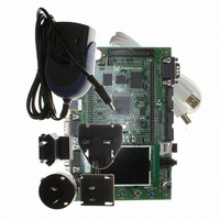
STM3210E-EVAL
Description
BOARD EVALUTION FOR STM32 512K
Manufacturer
STMicroelectronics
Type
MCUr
Specifications of STM3210E-EVAL
Contents
Evaluation Board
Processor To Be Evaluated
STM32F103Z
Data Bus Width
32 bit
Interface Type
RS-232, USB
Silicon Manufacturer
ST Micro
Core Architecture
ARM
Core Sub-architecture
Cortex - M3
Silicon Core Number
STM32
Silicon Family Name
STM32F1xx
For Use With/related Products
STM32
Lead Free Status / RoHS Status
Lead free / RoHS Compliant
Other names
497-6438
Available stocks
Company
Part Number
Manufacturer
Quantity
Price
Company:

Part Number:
STM3210E-EVAL
Manufacturer:
STMicroelectronics
Quantity:
135
Company:
Part Number:
STM3210E-EVAL
Manufacturer:
STMicroelectronics
Quantity:
1


Hardware layout and configuration
2.12
2.13
2.14
2.15
12/48
Temperature sensor
One I
STM32F103ZGT6 is available on the board.
Analog input
Three BNC connectors CN2,CN3 and CN5 are connected to PC3, PC2 and PC1 of the
STM32F103ZGT6 as external analog input. The 50 ohm terminal resistor can be enabled by
closing the solder bridge JP23, JP24 and JP25 for each BNC connector. A low-pass filter
can be implemented for each BNC connector CN5, CN3 and CN2 by replacing R5 and C22,
R4 and C13, R3 and C9 with the right resistor and capacitor values, depending on the
requirements of your application.
IrDA
IrDA communication is supported by the IrDA transceiver U13 connected to USART3 of
STM32F103ZGT6. The IrDA transceiver can be enabled or disabled by JP21.
Table 10.
USB
The STM3210E-EVAL evaluation board supports USB2.0 compliant full speed
communication via a USB type B connector (CN14). The evaluation board can be powered
by this USB connection at 5 V DC with a 500 mA current limitation. USB disconnection
simulation can be implemented by disconnecting the 1.5 K pull-up resistor from USB+ line.
The USB disconnection simulation feature is enabled by setting JP14.
Table 11.
JP21
JP22
JP14
Jumper
Jumper
2
C interface temperature sensor STLM75 (–55°C to +125°C) connected to I
Enables/disables the IrDA transceiver.
IrDA is enabled when JP21 is fitted (default setting).
IrDA is disabled when JP21 is not fitted.
IrDA_RX is enabled when JP22 is closed.
I/O pin PC11 is data line 3 of the MicroSD Card when JP22 is open (default setting).
The USB 1.5K pull-up resistor is always connected to USB+ line when
JP14 is set as shown.
The USB 1.5K pull-up resistor can be disconnected by software from
USB+ line when JP14 is set as shown. In this case, the USB
connect/disconnect feature is managed by standard IO port PB14
(default setting).
IrDA related jumpers
USB related jumpers
Doc ID 14220 Rev 5
Description
Description
1 2 3
1 2 3
2
C of
UM0488
Related parts for STM3210E-EVAL
Image
Part Number
Description
Manufacturer
Datasheet
Request
R

Part Number:
Description:
KIT STARTER FOR STM32 512K FLASH
Manufacturer:
STMicroelectronics
Datasheet:

Part Number:
Description:
KIT STARTER FOR STM32F10XE MCU
Manufacturer:
STMicroelectronics
Datasheet:

Part Number:
Description:
STARTER KIT FOR STM32
Manufacturer:
STMicroelectronics
Datasheet:

Part Number:
Description:
KIT STARTER FOR STM32F10XE MCU
Manufacturer:
STMicroelectronics
Datasheet:

Part Number:
Description:
DEV KIT FOR STM32
Manufacturer:
STMicroelectronics
Datasheet:

Part Number:
Description:
MCU ARM 128KB FLASH MEM 64-LQFP
Manufacturer:
STMicroelectronics
Datasheet:

Part Number:
Description:
MCU ARM 32BIT 128KB FLASH 64BGA
Manufacturer:
STMicroelectronics
Datasheet:

Part Number:
Description:
MCU ARM 32BIT 256K FLASH 144LQFP
Manufacturer:
STMicroelectronics
Datasheet:

Part Number:
Description:
KIT STARTER FOR STM32F10X
Manufacturer:
STMicroelectronics
Datasheet:

Part Number:
Description:
MCU ARM 128K FLASH/TIMER
Manufacturer:
STMicroelectronics
Datasheet:

Part Number:
Description:
MCU ARM 128KB FLASH MEM 100-LQFP
Manufacturer:
STMicroelectronics
Datasheet:

Part Number:
Description:
MCU 32BIT ARM 64K FLASH 36VFQFPN
Manufacturer:
STMicroelectronics
Datasheet:
Part Number:
Description:
MCU ARM 32BIT 32KB FLASH 48LQFP
Manufacturer:
STMicroelectronics
Datasheet:
Part Number:
Description:
MCU ARM 32BIT 64KB FLASH 64LQFP
Manufacturer:
STMicroelectronics
Datasheet:
Part Number:
Description:
MCU ARM 32BIT 384KB FLASH 64LQFP
Manufacturer:
STMicroelectronics
Datasheet: