STM3210E-EVAL STMicroelectronics, STM3210E-EVAL Datasheet - Page 7
STM3210E-EVAL
Manufacturer Part Number
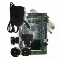
STM3210E-EVAL
Description
BOARD EVALUTION FOR STM32 512K
Manufacturer
STMicroelectronics
Type
MCUr
Specifications of STM3210E-EVAL
Contents
Evaluation Board
Processor To Be Evaluated
STM32F103Z
Data Bus Width
32 bit
Interface Type
RS-232, USB
Silicon Manufacturer
ST Micro
Core Architecture
ARM
Core Sub-architecture
Cortex - M3
Silicon Core Number
STM32
Silicon Family Name
STM32F1xx
For Use With/related Products
STM32
Lead Free Status / RoHS Status
Lead free / RoHS Compliant
Other names
497-6438
Available stocks
Company
Part Number
Manufacturer
Quantity
Price
Company:

Part Number:
STM3210E-EVAL
Manufacturer:
STMicroelectronics
Quantity:
135
Company:
Part Number:
STM3210E-EVAL
Manufacturer:
STMicroelectronics
Quantity:
1


UM0488
2.1
Power supply
The STM3210E-EVAL evaluation board is designed to be powered by 5V DC power supply
and to be protected by PolyZen U15 in the event of wrong power plug-in. It is possible to
configure the evaluation board to use any of following three sources for the power supply:
The power supply is configured by setting the related jumpers JP13, JP12 and JP1 as
described in
powered correctly.
Table 1.
JP13
JP12
JP1
Jumper
5V DC power adapter connected to CN17, the power jack on the board (PSU on silk
screen for power supply unit).
5V DC power with 500 mA limitation from CN14, the type-B USB connector (USB on
silkscreen).
5V DC power from both CN10 and CN11, the extension connector for daughterboard
(DTB for daughterboard on silkscreen).
For power supply from the daughterboard connectors(CN10 and CN11)
to STM3210E-EVAL only, JP13 is set as shown.
For power supply from USB (CN14) to STM3210E-EVAL only, JP13 is set
as shown.
For power supply from power supply jack(CN17) to both STM3210E-
EVAL and daughterboard connected on CN10 and CN11, JP13 is set as
shown (daughterboard must not have its own power supply
connected).
Enables consumption measurements of both VDD and VDDA.
Default setting: Fitted
V
setting).
V
bat
bat
Table
Power related jumpers
is connected to 3.3V power when JP1 is set as shown (default
is connected to battery when JP1 is set as shown.
1. The LED LD5 is lit when the STM3210E-EVAL evaluation board is
JP13 is used to select one of the three possible power supply resources.
For power supply jack(CN17) to the STM3210E-EVAL only, JP13 is set
as shown (default setting).
Doc ID 14220 Rev 5
Description
Hardware layout and configuration
1 2 3
1 2 3
7/48
Related parts for STM3210E-EVAL
Image
Part Number
Description
Manufacturer
Datasheet
Request
R

Part Number:
Description:
KIT STARTER FOR STM32 512K FLASH
Manufacturer:
STMicroelectronics
Datasheet:

Part Number:
Description:
KIT STARTER FOR STM32F10XE MCU
Manufacturer:
STMicroelectronics
Datasheet:

Part Number:
Description:
STARTER KIT FOR STM32
Manufacturer:
STMicroelectronics
Datasheet:

Part Number:
Description:
KIT STARTER FOR STM32F10XE MCU
Manufacturer:
STMicroelectronics
Datasheet:

Part Number:
Description:
DEV KIT FOR STM32
Manufacturer:
STMicroelectronics
Datasheet:

Part Number:
Description:
MCU ARM 128KB FLASH MEM 64-LQFP
Manufacturer:
STMicroelectronics
Datasheet:

Part Number:
Description:
MCU ARM 32BIT 128KB FLASH 64BGA
Manufacturer:
STMicroelectronics
Datasheet:

Part Number:
Description:
MCU ARM 32BIT 256K FLASH 144LQFP
Manufacturer:
STMicroelectronics
Datasheet:

Part Number:
Description:
KIT STARTER FOR STM32F10X
Manufacturer:
STMicroelectronics
Datasheet:

Part Number:
Description:
MCU ARM 128K FLASH/TIMER
Manufacturer:
STMicroelectronics
Datasheet:

Part Number:
Description:
MCU ARM 128KB FLASH MEM 100-LQFP
Manufacturer:
STMicroelectronics
Datasheet:

Part Number:
Description:
MCU 32BIT ARM 64K FLASH 36VFQFPN
Manufacturer:
STMicroelectronics
Datasheet:
Part Number:
Description:
MCU ARM 32BIT 32KB FLASH 48LQFP
Manufacturer:
STMicroelectronics
Datasheet:
Part Number:
Description:
MCU ARM 32BIT 64KB FLASH 64LQFP
Manufacturer:
STMicroelectronics
Datasheet:
Part Number:
Description:
MCU ARM 32BIT 384KB FLASH 64LQFP
Manufacturer:
STMicroelectronics
Datasheet: