EVAL-AD7706EB Analog Devices Inc, EVAL-AD7706EB Datasheet - Page 28
EVAL-AD7706EB
Manufacturer Part Number
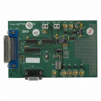
EVAL-AD7706EB
Description
BOARD EVAL FOR AD7706
Manufacturer
Analog Devices Inc
Datasheet
1.EVAL-AD7705EB.pdf
(32 pages)
Specifications of EVAL-AD7706EB
Number Of Adc's
1
Number Of Bits
16
Sampling Rate (per Second)
500
Data Interface
Serial
Inputs Per Adc
3 Differential
Input Range
0 ~ 5.25 V
Power (typ) @ Conditions
6.5mW @ 500SPS
Voltage Supply Source
Single
Operating Temperature
-40°C ~ 85°C
Utilized Ic / Part
AD7706
Lead Free Status / RoHS Status
Contains lead / RoHS non-compliant


AD7705/AD7706
/* This program has read and write routines for the 68HC11 to interface to the AD7705 and the sample program sets the various
registers and then reads 1000 samples from one channel. */
#include <math.h>
#include <io6811.h>
#define NUM_SAMPLES 1000 /* change the number of data samples */
#define MAX_REG_LENGTH 2 /* this says that the max length of a register is 2 bytes */
Writetoreg (int);
Read (int,char);
char *datapointer = store;
char store[NUM_SAMPLES*MAX_REG_LENGTH + 30];
void main()
{
an output */
char a;
DDRC = 0x04; /* PC2 is an output the rest of the port bits are inputs */
PORTC | = 0x04; /* make the /CS line high */
Writetoreg(0x20); /* Active Channel is Ain1(+)/Ain1(-), next operation as write to the clock register */
Writetoreg(0x0C); /* master clock enabled, 4.9512MHz Clock, set output rate to 50Hz*/
Writetoreg(0x10); /* Active Channel is Ain1(+)/Ain1(-), next operation as write to the setup register */
Writetoreg(0x40); /* gain = 1, bipolar mode, buffer off, clear FSYNC and perform a Self Calibration*/
while(PORTC & 0x10); /* wait for /DRDY to go low */
for(a=0;a<NUM_SAMPLES;a++);
}
Writetoreg(int byteword);
{
int q;
SPCR = 0x3f;
SPCR = 0X7f; /* this sets the WiredOR mode(DWOM=1), Master mode(MSTR=1), SCK idles high(CPOL=1), /SS can be low
always (CPHA=1), lowest clock speed(slowest speed which is master clock /32 */
DDRD = 0x18; /* SCK, MOSI outputs */
q = SPSR;
q = SPDR; /* the read of the staus register and of the data register is needed to clear the interrupt which tells the user that the
data transfer is complete */
PORTC &= 0xfb; /* /CS is low */
SPDR = byteword; /* put the byte into data register */
while(!(SPSR & 0x80)); /* wait for /DRDY to go low */
PORTC |= 0x4; /* /CS high */
}
Read(int amount, int reglength)
{
int q;
SPCR = 0x3f;
SPCR = 0x7f; /* clear the interupt */
DDRD = 0x10; /* MOSI output, MISO input, SCK output */
while(PORTC & 0x10); /* wait for /DRDY to go low */
PORTC & 0xfb ; /* /CS is low */
for(b=0;b<reglength;b++)
PORTC|=4; /* /CS is high */
}
/* the only pin that is programmed here from the 68HC11 is the /CS and this is why the PC2 bit of PORTC is made as
{
Writetoreg(0x38); /*set the next operation for 16 bit read from the data register */
Read(NUM_SAMPES,2);
}
{
SPDR = 0;
while(!(SPSR & 0x80)); /* wait until port ready before reading */
*datapointer++=SPDR; /* read SPDR into store array via datapointer */
}
Table XVII. C Code for Interfacing AD7705 to 68HC11
–28–
REV. A
Related parts for EVAL-AD7706EB
Image
Part Number
Description
Manufacturer
Datasheet
Request
R

Part Number:
Description:
ENERCHIP CC EVAL KIT
Manufacturer:
Cymbet Corporation
Datasheet:

Part Number:
Description:
BOARD EVAL FOR AD976
Manufacturer:
Analog Devices Inc
Datasheet:

Part Number:
Description:
BOARD EVAL FOR ADXL345
Manufacturer:
Analog Devices Inc
Datasheet:

Part Number:
Description:
ENERCHIP CC SEH EVAL KIT
Manufacturer:
Cymbet Corporation
Datasheet:

Part Number:
Description:
ENERCHIP EP ENERGY HARVEST EVAL
Manufacturer:
Cymbet Corporation
Datasheet:

Part Number:
Description:
EVAL BOARD FOR TW6864-LB2-GR
Manufacturer:
Intersil
Datasheet:
Part Number:
Description:
EVAL BOARD FOR TW8816-LB3-GR
Manufacturer:
Intersil
Datasheet:
Part Number:
Description:
EVAL BOARD FOR TW8817-TA3-GRS
Manufacturer:
Intersil
Datasheet:

Part Number:
Description:
EVALUATION MODULE FOR ADUM4160
Manufacturer:
Analog Devices Inc
Datasheet:

Part Number:
Description:
BOARD EVALUATION ADCMP581BCP
Manufacturer:
Analog Devices Inc
Datasheet:
Part Number:
Description:
BOARD EVALUATION ADM1041
Manufacturer:
Analog Devices Inc
Datasheet:

Part Number:
Description:
EVAL BOARD FOR STM32F107VCT
Manufacturer:
STMicroelectronics
Datasheet:
Part Number:
Description:
BOARD EVAL FOR AD1954
Manufacturer:
Analog Devices Inc
Datasheet:
Part Number:
Description:
BOARD EVAL FOR AD1955
Manufacturer:
Analog Devices Inc
Datasheet:

Part Number:
Description:
BOARD EVAL FOR AD7655
Manufacturer:
Analog Devices Inc
Datasheet: