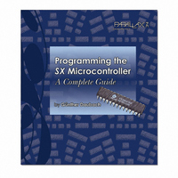
45181 Parallax Inc, 45181 Datasheet - Page 98

45181
Manufacturer Part Number
45181
Description
SX TECH TOOL KIT NO POWER
Manufacturer
Parallax Inc
Series
SXr
Type
Microcontrollerr
Datasheet
1.45180.pdf
(184 pages)
Specifications of 45181
Contents
SX Book, SX Key, SX Tech Board, Samples, Resonators, Cable and Manual
Product
Microcontroller Basic Stamps
Operating Supply Voltage
5 V
For Use With/related Products
SX MCUs
Lead Free Status / RoHS Status
Lead free / RoHS Compliant
- Current page: 98 of 184
- Download datasheet (2Mb)
10 SX Special Features and Coding Tips
duty cycle, the sum R1+R2 must remain constant, i.e. to change the duty cycle, increase the value of one
register, and decrease the value of the other register by the same amount.
In PWM mode, the 16-bit counter is clocked through the prescaler from the system clock. The prescaler
can be set to divide-by factors from 1 to 256 in steps of powers of two.
10.3.2 Software Timer Mode
This mode is similar to the PWM mode with the difference that the output signal is not toggled. Instead,
the application program must react on the interrupts that indicate a match between the counter and R1,
or between the counter and R2. An additional interrupt is generated when the counter overflows from
$ffff to $0000.
10.3.3 External Event Counter
Again, this mode is similar to the PWM mode, but here, the 16-bit counter is clocked from an external
signal instead of the system clock. The external input can be configured in order to have positive or
negative transitions increment the counter.
10.3.4 Capture/Compare Mode
In this mode, the 16-bit counter is clocked by the prescaled system clock and it keeps incrementing
without being reset. A valid transition at one of the two inputs causes the current counter contents to be
stored in the associated capture register. This makes it easy to determine the time difference between
two external events.
In addition, the counter contents are continuously compared against the contents of register R1. If both
are equal, an interrupt is generated (if enabled), and the output signal is toggled. Unlike the PWM
mode, the counter is not reset in this case, it keeps incrementing.
In order to obtain a fixed period between the interrupts and output toggles, the ISR must load a new
value into R1 whenever an interrupt is triggered.
The two inputs Capture 1 and Capture 2, can be configured to trigger on positive or negative transi-
tions.
Capture register 1 is a separate register dedicated to capture the counter contents only, where Register
R2 is used for the capture register 2.
As an option, each capture event can also issue an interrupt and various flags allow the ISR to
determine the cause of the interrupt.
In addition, a 16-bit counter overflow can also trigger an interrupt, and set a flag. This is important
when the time between two external events is long enough to allow for one or more counter overflows.
If the ISR keeps track of the number of overflows, it is possible to calculate the time elapsed between
two external events.
Page 98 SX-Key/Blitz Development System Manual 2.0 Parallax, Inc.
Related parts for 45181
Image
Part Number
Description
Manufacturer
Datasheet
Request
R

Part Number:
Description:
Terminals 3 Pin Single Row Header (long)
Manufacturer:
Parallax Inc

Part Number:
Description:
Headers & Wire Housings 16 Pin Single Row Header
Manufacturer:
Parallax Inc

Part Number:
Description:
Microcontroller Modules & Accessories DISCONTINUED BY PARALLAX
Manufacturer:
Parallax Inc

Part Number:
Description:
BOOK UNDERSTANDING SIGNALS
Manufacturer:
Parallax Inc
Datasheet:

Part Number:
Description:
COMPETITION RING FOR SUMOBOT
Manufacturer:
Parallax Inc
Datasheet:

Part Number:
Description:
TEXT INFRARED REMOTE FOR BOE-BOT
Manufacturer:
Parallax Inc
Datasheet:

Part Number:
Description:
Microcontroller Modules & Accessories DISCONTINUED BY PARALLAX
Manufacturer:
Parallax Inc

Part Number:
Description:
BOOK UNDERSTANDING SIGNALS
Manufacturer:
Parallax Inc
Datasheet:

Part Number:
Description:
BOARD EXPERIMENT+LCD NX-1000
Manufacturer:
Parallax Inc
Datasheet:

Part Number:
Description:
IC MCU 2K FLASH 50MHZ SO-18
Manufacturer:
Parallax Inc
Datasheet:


