MCIMX31LITEKITC Freescale Semiconductor, MCIMX31LITEKITC Datasheet - Page 19
MCIMX31LITEKITC
Manufacturer Part Number
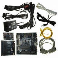
MCIMX31LITEKITC
Description
BOARD DEV FOR I.MX31
Manufacturer
Freescale Semiconductor
Type
MCUr
Datasheet
1.MCIMX31LITEKITC.pdf
(122 pages)
Specifications of MCIMX31LITEKITC
Contents
Module and Misc Hardware
For Use With/related Products
i.MX31
Lead Free Status / RoHS Status
Lead free / RoHS Compliant


4.2
Any MCIMX31 board design must comply with the power-up and power-down sequence guidelines as
described in this section to guarantee reliable operation of the device. Any deviation from these sequences
may result in any or all of the following situations:
4.2.1
The Power On Reset (POR) pin must be kept asserted (low) throughout the power up sequence. Power up
logic must guarantee that all power sources reach their target values prior to the release (de-assertion) of
POR.
show the power-up sequence for silicon Revision 2.0.
Freescale Semiconductor
•
•
•
Figure 2
Cause excessive current during power up phase
Prevent the device from booting
Cause irreversible damage to the MCIMX31 (worst-case scenario)
Supply Power-Up/Power-Down Requirements and Restrictions
Powering Up
shows the power-up sequence for silicon Revisions 1.2 and previous.
Stages need to be performed in the order shown; however, within each stage,
supplies can be powered up in any order. For example, supplies IOQVDD,
NVCC1, and NVCC3 through NVCC10 do not need to be powered up in the
order shown.
NVCC6 and NVCC9 must be at the same voltage potential. These supplies
are connected together on-chip to optimize ESD damage immunity.
MCIMX31/MCIMX31L Technical Data, Rev. 4.1
CAUTION
NOTE
Electrical Characteristics
Figure 3
and
Figure 4
19
Related parts for MCIMX31LITEKITC
Image
Part Number
Description
Manufacturer
Datasheet
Request
R

Part Number:
Description:
Multimedia Applications Processors
Manufacturer:
FREESCALE [Freescale Semiconductor, Inc]
Datasheet:

Part Number:
Description:
Manufacturer:
Freescale Semiconductor, Inc
Datasheet:
Part Number:
Description:
Manufacturer:
Freescale Semiconductor, Inc
Datasheet:
Part Number:
Description:
Manufacturer:
Freescale Semiconductor, Inc
Datasheet:
Part Number:
Description:
Manufacturer:
Freescale Semiconductor, Inc
Datasheet:
Part Number:
Description:
Manufacturer:
Freescale Semiconductor, Inc
Datasheet:
Part Number:
Description:
Manufacturer:
Freescale Semiconductor, Inc
Datasheet:
Part Number:
Description:
Manufacturer:
Freescale Semiconductor, Inc
Datasheet:
Part Number:
Description:
Manufacturer:
Freescale Semiconductor, Inc
Datasheet:
Part Number:
Description:
Manufacturer:
Freescale Semiconductor, Inc
Datasheet:
Part Number:
Description:
Manufacturer:
Freescale Semiconductor, Inc
Datasheet:
Part Number:
Description:
Manufacturer:
Freescale Semiconductor, Inc
Datasheet:
Part Number:
Description:
Manufacturer:
Freescale Semiconductor, Inc
Datasheet:
Part Number:
Description:
Manufacturer:
Freescale Semiconductor, Inc
Datasheet:
Part Number:
Description:
Manufacturer:
Freescale Semiconductor, Inc
Datasheet: