MCIMX31LITEKITC Freescale Semiconductor, MCIMX31LITEKITC Datasheet - Page 55
MCIMX31LITEKITC
Manufacturer Part Number
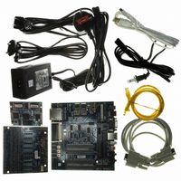
MCIMX31LITEKITC
Description
BOARD DEV FOR I.MX31
Manufacturer
Freescale Semiconductor
Type
MCUr
Datasheet
1.MCIMX31LITEKITC.pdf
(122 pages)
Specifications of MCIMX31LITEKITC
Contents
Module and Misc Hardware
For Use With/related Products
i.MX31
Lead Free Status / RoHS Status
Lead free / RoHS Compliant


Figure 41
Table 41
4.3.10.1 Half-Rate Clocking Mode
When half-rate clocking is used, the trace data signals are sampled by the TPA on both the rising and falling
edges of TRACECLK, where TRACECLK is half the frequency of the clock shown in
4.3.11
FIR implements asynchronous infrared protocols (FIR, MIR) that are defined by IrDA
Association). Refer to http://www.IrDA.org for details on FIR and MIR protocols.
4.3.12
Freescale Semiconductor
1
The program length is defined by the value defined in the epm_pgm_length[2:0] bits of the IIM module. The value to program
is based on a 32 kHz clock source (4 * 1/32 kHz = 125 µs).
Ref. Num
1
T
T
T
ID
T
T
cyc
wh
wl
lists the timing parameters.
r
f
depicts the setup and hold requirements of the trace data pins with respect to TRACECLK, and
FIR Electrical Specifications
Fusebox Electrical Specifications
Clock period
Low pulse width
High pulse width
Clock and data rise time
Clock and data fall time
ID
T
T
s
h
Program time for eFuse
Data setup
Data hold
Description
Parameter
Table 40. ETM TRACECLK Timing Parameters
Table 41. ETM Trace Data Timing Parameters
Table 42. Fusebox Timing Characteristics
MCIMX31/MCIMX31L Technical Data, Rev. 4.1
Figure 41. Trace Data Timing Diagram
1
Parameter
Symbol
t
program
Frequency dependent
Minimum
125
Min
—
—
2
2
Min
2
1
Typical
—
Max
—
—
Electrical Characteristics
Maximum
Max
®
—
—
—
3
3
Figure
—
(Infrared Data
Unit
ns
ns
Unit
41.
ns
ns
ns
ns
ns
Units
µs
55
Related parts for MCIMX31LITEKITC
Image
Part Number
Description
Manufacturer
Datasheet
Request
R

Part Number:
Description:
Multimedia Applications Processors
Manufacturer:
FREESCALE [Freescale Semiconductor, Inc]
Datasheet:

Part Number:
Description:
Manufacturer:
Freescale Semiconductor, Inc
Datasheet:
Part Number:
Description:
Manufacturer:
Freescale Semiconductor, Inc
Datasheet:
Part Number:
Description:
Manufacturer:
Freescale Semiconductor, Inc
Datasheet:
Part Number:
Description:
Manufacturer:
Freescale Semiconductor, Inc
Datasheet:
Part Number:
Description:
Manufacturer:
Freescale Semiconductor, Inc
Datasheet:
Part Number:
Description:
Manufacturer:
Freescale Semiconductor, Inc
Datasheet:
Part Number:
Description:
Manufacturer:
Freescale Semiconductor, Inc
Datasheet:
Part Number:
Description:
Manufacturer:
Freescale Semiconductor, Inc
Datasheet:
Part Number:
Description:
Manufacturer:
Freescale Semiconductor, Inc
Datasheet:
Part Number:
Description:
Manufacturer:
Freescale Semiconductor, Inc
Datasheet:
Part Number:
Description:
Manufacturer:
Freescale Semiconductor, Inc
Datasheet:
Part Number:
Description:
Manufacturer:
Freescale Semiconductor, Inc
Datasheet:
Part Number:
Description:
Manufacturer:
Freescale Semiconductor, Inc
Datasheet:
Part Number:
Description:
Manufacturer:
Freescale Semiconductor, Inc
Datasheet: