PCDIDE COMPILER Custom Computer Services Inc (CCS), PCDIDE COMPILER Datasheet - Page 162
PCDIDE COMPILER
Manufacturer Part Number
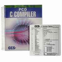
PCDIDE COMPILER
Description
PCD C-COMPILER PIC24, DSPIC
Manufacturer
Custom Computer Services Inc (CCS)
Type
Compilerr
Datasheet
1.PCD_COMMAND_LINE_COMPILER.pdf
(373 pages)
Specifications of PCDIDE COMPILER
For Use With/related Products
Microchip PIC24/dsPIC®
Lead Free Status / RoHS Status
Not applicable / Not applicable
Other names
429-1008


Purpose:
Examples:
Example Files:
Also See:
148
The SPI library contains functions to implement an SPI bus. After setting all of the
proper parameters in #USE SPI, the spi_xfer() function can be used to both
transfer and receive data on the SPI bus.
The SPI1 and SPI2 options will use the SPI hardware onboard the PIC. The most
common pins present on hardware SPI are: DI, DO, and CLK. These pins don’t
need to be assigned values through the options; the compiler will automatically
assign hardware-specific values to these pins. Consult your PIC’s data sheet as
to where the pins for hardware SPI are. If hardware SPI is not used, then software
SPI will be used. Software SPI is much slower than hardware SPI, but software
SPI can use any pins to transfer and receive data other than just the pins tied to
the PIC’s hardware SPI pins.
The MODE option is more or less a quick way to specify how the stream is going
to sample data. MODE=0 sets IDLE=0 and SAMPLE_RISE. MODE=1 sets
IDLE=0 and SAMPLE_FALL. MODE=2 sets IDLE=1 and SAMPLE_FALL.
MODE=3 sets IDLE=1 and SAMPLE_RISE. There are only these 4 MODEs.
SPI cannot use the same pins for DI and DO. If needed, specify two streams: one
to send data and another to receive data.
The pins must be specified with DI, DO, CLK or SPIx, all other options are
defaulted as indicated above.
#use spi(DI=PIN_B1, DO=PIN_B0, CLK=PIN_B2, ENABLE=PIN_B4,
BITS=16)
// uses software SPI
#use spi(FORCE_HW, BITS=16, stream=SPI_STREAM)
// uses hardware SPI and gives this stream the name SPI_STREAM
None
spi_xfer()
LOAD_ACTIVE=n
ENABLE_ACTIVE=n
IDLE=n
ENABLE_DELAY=n
DATA_HOLD=n
LSB_FIRST
MSB_FIRST
STREAM=id
SPI1
SPI2
FORCE_HW
Active state for LOAD pin (0, 1).
Active state for ENABLE pin (0, 1). (default=0)
Inactive state for CLK pin (0, 1). (default=0)
Time in us to delay after ENABLE is activated.
(default=0)
Time between data change and clock change
LSB is sent first.
MSB is sent first. (default)
Specify a stream name for this protocol.
Use the hardware pins for SPI Port 1
Use the hardware pins for SPI Port 2
Use the pic hardware SPI.
Related parts for PCDIDE COMPILER
Image
Part Number
Description
Manufacturer
Datasheet
Request
R

Part Number:
Description:
PROTOTYPING BOARD FOR PIC MCU
Manufacturer:
Custom Computer Services Inc (CCS)
Part Number:
Description:
Extra CCS C Manual
Manufacturer:
Custom Computer Services Inc (CCS)
Part Number:
Description:
MACH X Programmer
Manufacturer:
Custom Computer Services Inc (CCS)
Part Number:
Description:
PCD For 24-bit (PIC24/dsPIC)
Manufacturer:
Custom Computer Services Inc (CCS)
Part Number:
Description:
LOAD-n-GO Programmer
Manufacturer:
Custom Computer Services Inc (CCS)
Part Number:
Description:
EMBEDDED INTERNET DEVELOPMENT KIT W/PCWH
Manufacturer:
Custom Computer Services Inc (CCS)
Part Number:
Description:
PIC24F Development Kit With PCWHD
Manufacturer:
Custom Computer Services Inc (CCS)
Part Number:
Description:
PIC24F Development Kit With PCDIDE
Manufacturer:
Custom Computer Services Inc (CCS)
Part Number:
Description:
PIC24H Development Kit With PCWHD
Manufacturer:
Custom Computer Services Inc (CCS)
Part Number:
Description:
USB Master Prototyping Board
Manufacturer:
Custom Computer Services Inc (CCS)