CHIPPROG-40 Phyton Inc, CHIPPROG-40 Datasheet - Page 90
CHIPPROG-40
Manufacturer Part Number
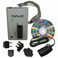
CHIPPROG-40
Description
PROGRAMMER STANDALONE 40-DIP
Manufacturer
Phyton Inc
Type
Universal, Stand Aloner
Specifications of CHIPPROG-40
Contents
Programmer, Cables, CD, Power Adapter
Ic Product Type
Programmer, Universal
Ic Interface Type
USB
Features
Embedded Script Language For Automation Of Routine Operations, Splits Files To Multiple Images
Rohs Compliant
Yes
For Use With/related Products
EEPROM, EPROM, FLASH, MCU, NVRAM
Lead Free Status / RoHS Status
Lead free / RoHS Compliant


5.4.1.1.1.3 Error Checking and Correction
5.4.1.1.2 Invalid block map
90
The programming algorithm works in the following way:
1) it splits blocks of the device in three areas: User Block Area, Block Reservoir and Reserved
Block Area;
2) it reads the
RBA Marker - is 0FDFEh (there is an equivalent term for this parameter used in some NAND Flash
device data sheets: Transition Field).
Count Field - starts from 1 and increments by one for each page of the map table.
Invalid Block - Number of the invalid block in the UBA being replaced.
Replaced Block - Number of the valid block in the Block Reservoir that replaces the invalid block
above.
The Invalid Block - Replaced Block pairs follow each other till the page break.
When the programming equipment detects an invalid block in the User Block Area it appoints the first
available valid block in the Block Reservoir and updates the RBA table to keep track of relation
between invalid blocks in the User Block Area and replaced good ones in the Block Reservoir.
To maintain the stored code integrity it is recommended to use known Error Checking and
Correction (ECC) algorithms. Most NAND Flash device manufacturers publish application notes that
describe the ECC algorithms suitable for using their devices in different applications. To implement a
particular ECC algorithm please check the manufacturer's website. All the ECC-related information are
written into the
ChipProg programmers create the
continues bit array. Valid (good) blocks are represented by zeros (0), invalid (bad) - by ones (1). See
the tab Invalid Block Map in the memory buffer:
Field: RBA Marker Count Field Invalid Block Replaced
Size:
The Block Reservoir - a linear memory array that follows right after the User Block Area; good
blocks from the Block Reservoir replaces invalid blocks from the User Block Area;
The Reserved Block Area (RBA) - this part of the device's memory stores the information about
bad blocks in the User Block Area replaced by good blocks from the Block Reservoir. This map is
represented by pair of addresses of the invalid UBA's blocks and corresponding good blocks from
the data reservoir. The first good block in the RBA stores the the RBA map table, the second a
duplicate of it in case of the RBA table corruption.
ChipProg Device Programmers
2 б йт
Spare Area
Spare
2 б йт
Area.
2 б йт
invalid block
2 б йт
Block
map into the buffer layer Invalid Block Map as a
Invalid Block
2 б йт
© 2010 Phyton, Inc. Microsystems and Development Tools
Replaced
2 б йт
Block
.......
.......
Invalid Block
2 б йт
Replaced
2 б йт
Block
Related parts for CHIPPROG-40
Image
Part Number
Description
Manufacturer
Datasheet
Request
R

Part Number:
Description:
Diodes (General Purpose, Power, Switching) HIREL
Manufacturer:
Infineon Technologies
Part Number:
Description:
RF Bipolar Small Signal HIREL
Manufacturer:
Infineon Technologies
Part Number:
Description:
RF Bipolar Small Signal HIREL
Manufacturer:
Infineon Technologies
Part Number:
Description:
RF Bipolar Small Signal HIREL
Manufacturer:
Infineon Technologies