R99-11 Omron, R99-11 Datasheet - Page 13
R99-11
Manufacturer Part Number
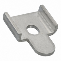
R99-11
Description
MOUNTING BRACKET FOR G3NA RELAY
Manufacturer
Omron
Series
G3NAr
Specifications of R99-11
Accessory Type
Mounting Bracket, Plate
Associated Relay Series
G3NA-240B, G3NA-440B(-2)
Termination Style
Screw
Mounting Style
Screw
Width
16 mm
For Use With/related Products
G3NA-240B and G3NA-440B
For Use With
Z2588 - RELAY SSR 40A 5VDCZ2587 - RELAY SSR 40A 230VACZ173 - RELAY SSR 40A@220VAC ZERO CROSSZ174 - RELAY SSR 40A@220VAC ZERO CROSSZ172 - RELAY SSR 40A@220VAC ZERO CROSS
Lead Free Status / RoHS Status
Lead free / RoHS Compliant
Color
-
Lead Free Status / Rohs Status
Lead free / RoHS Compliant
Other names
R99-11
R9911
R9911NC
Z2000
R9911
R9911NC
Z2000


Operating and Storage Locations
Do not use or store the G3NA in the following locations. Doing so
may result in damage, malfunction, or deterioration of performance
characteristics.
■ Precautions for Correct Use
Please observe the following precautions to prevent failure to oper-
ate, malfunction, or undesirable effect on product performance.
Before Actual Operation
1. The G3NA in operation may cause an unexpected accident.
2. Unless otherwise specified, the ratings in this catalog are tested
Mounting Method
SSR Mounting Pitch (Panel Mounting)
Duct
• Do not use or store in locations subject to direct sunlight.
• Do not use in locations subject to ambient temperatures outside
• Do not use in locations subject to relative humidity outside the
• Do not store in locations subject to ambient temperatures outside
• Do not use or store in locations subject to corrosive or flammable
• Do not use or store in locations subject to dust (especially iron
• Do not use or store in locations subject to shock or vibration.
• Do not use or store in locations subject to exposure to water, oil, or
• Do not use or store in locations subject to high temperatures or
• Do not use or store in locations subject to salt damage.
• Do not use or store in locations subject to rain or water drops.
80 mm min.
the range –20 to 60°C.
range 45% to 85% or locations subject to condensation as the
result of severe changes in temperature.
the range –30 to 70°C.
gases.
dust) or salts.
chemicals.
high humidity.
Therefore it is necessary to test the G3NA under the variety of
conditions that are possible. As for the characteristics of the
G3NA, it is necessary to consider differences in characteristics
between individual SSRs.
values in a temperature range between 15°C and 30°C, a relative
humidity range between 25% and 85%, and an atmospheric pres-
sure range between 88 and 106 kPa (standard test conditions
according to JIS C5442). It will be necessary to provide the above
conditions as well as the load conditions if the user wants to con-
firm the ratings of specific G3NAs.
60 mm min.
30 mm min.
Vertical direction
Relationship between SSRs and Duct Height
Ventilation Outside the Control Panel
If the air inlet or air outlet has a filter, clean the filter regularly to pre-
vent it from clogging to ensure an efficient flow of air.
Do not locate any objects around the air inlet or air outlet, otherwise
the objects may obstruct the proper ventilation of the control panel.
A heat exchanger, if used, should be located in front of the SSRs to
ensure the efficiency of the heat exchanger.
• Please reduce the ambient temperature of SSRs. The rated load
• An SSR uses a semiconductor in the output element. This causes
Example: For 10 SSRs with load currents of 10 A,
Size of fans: 92 mm
Ambient temperature of control panel: 30 °C
If there are other instruments that generate heat in the control panel
other than SSRs, additional ventilation will be required.
Incorrect Example
Required number
of fans per SSR
Do not surround the SSR
with ducts, otherwise the
heat radiation of the SSR
will be adversely affected.
Load current (A)
current of an SSR is measured at an ambient temperature of 40°C.
the temperature inside the control panel to increase due to heating
resulting from the passage of electrical current through the load. To
restrict heating, attach a fan to the ventilation outlet or air inlet of
the control panel to ventilate the panel. This will reduce the ambient
temperature of the SSRs and thus increase reliability. (Generally,
each 10 °C reduction in temperature will double the expected life.)
Air inlet
0.16 x 10 = 1.6
Thus, 2 fans would be required.
Vertical
direction
Duct
Duct
Solid State Relay
2
0.08
, Air volume: 0.7 m
5 A
Duct
Use short ducts.
Countermeasure 1
Be aware of airflow
0.16
10 A
50 mm max.
(A height of no
more than half
the SSR's height
is recommended.)
Duct
0.31
20 A
3
/min,
G3NA
0.62
40 A
Countermeasure 2
If the ducts cannot be
shortened, place the SSR on
a metal base so that it is not
surrounded by the ducts.
Base
Ventilation
outlet
(axial fan)
1.2
75 A
Airflow
Duct
Duct
463
1.44
90 A
Related parts for R99-11
Image
Part Number
Description
Manufacturer
Datasheet
Request
R

Part Number:
Description:
1 Sheet Of 120 Plastic Labels
Manufacturer:
Omron
Datasheet:

Part Number:
Description:
MOUNTING BRACKET -G7J
Manufacturer:
Omron
Datasheet:
Part Number:
Description:
DUST COVER FOR G8P SERIES
Manufacturer:
Omron
Datasheet:

Part Number:
Description:
10 Sheets (484 Per)
Manufacturer:
Omron
Datasheet:

Part Number:
Description:
Mounting Bracket
Manufacturer:
Omron
Datasheet:

Part Number:
Description:
BRACKET FOR G7L
Manufacturer:
Omron
Datasheet:
Part Number:
Description:
Tool For P6DS Socket
Manufacturer:
Omron
Datasheet:
Part Number:
Description:
NAMEPLATE FOR MY
Manufacturer:
Omron
Datasheet:

Part Number:
Description:
G3NA MTG BRACKET
Manufacturer:
Omron
Datasheet:

Part Number:
Description:
G6S-2GLow Signal Relay
Manufacturer:
Omron Corporation
Datasheet:
Part Number:
Description:
Compact, Low-cost, SSR Switching 5 to 20 A
Manufacturer:
Omron Corporation
Datasheet:
Part Number:
Description:
Manufacturer:
Omron Corporation
Datasheet: