R99-11 Omron, R99-11 Datasheet - Page 14
R99-11
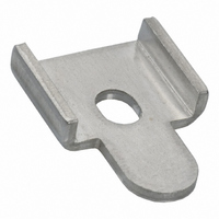
Manufacturer Part Number
R99-11
Description
MOUNTING BRACKET FOR G3NA RELAY
Manufacturer
Omron
Series
G3NAr
Specifications of R99-11
Accessory Type
Mounting Bracket, Plate
Associated Relay Series
G3NA-240B, G3NA-440B(-2)
Termination Style
Screw
Mounting Style
Screw
Width
16 mm
For Use With/related Products
G3NA-240B and G3NA-440B
For Use With
Z2588 - RELAY SSR 40A 5VDCZ2587 - RELAY SSR 40A 230VACZ173 - RELAY SSR 40A@220VAC ZERO CROSSZ174 - RELAY SSR 40A@220VAC ZERO CROSSZ172 - RELAY SSR 40A@220VAC ZERO CROSS
Lead Free Status / RoHS Status
Lead free / RoHS Compliant
Color
-
Lead Free Status / Rohs Status
Lead free / RoHS Compliant
Other names
R99-11
R9911
R9911NC
Z2000
R9911
R9911NC
Z2000


High-capacity Heat Sink
(Y92B-P250NF)
DIN-track Mounting
• Assembled DIN Tracks are heavy. Mount the DIN Tracks securely.
• Attach End Plates (PFP-M, order separately) to both ends of the
• To mount a Heat Sink to a DIN Track, press down at the point indi-
Applicable DIN Track
Mounting is possible on TE35-15Fe (IEC 60715) DIN tracks. DIN
tracks from the following manufacturers can be used.
Direct Mounting
• Prepare mounting holes as shown in the diagram. Tightening
• When mounting a Heat Sink directly, first remove the Fan Unit, then
• First, temporarily mount the Heat Sink with the bottom two screws
464
Schneider
WAGO
PHOENIX
Be sure that the Heat Sink is securely locked to the DIN Track.
Units on the DIN Track to hold them in place.
cated by arrow 1 in the diagram and then press in the Heat Sink at
the point indicated by arrow 2.
torque: 0.98 to 1.47 N•m
mount the Heat Sink by itself before attaching the Fan Unit again.
(Remove the two screws shown in the following diagram.)
and then attach the top two screws with the mounting bracket sand-
wiched between the Heat Sink and mounting surface. Finally,
tighten all four screws.
Manufacturer
Solid State Relay
Remove screws
Vertical
130
Heat Sink
AM1-DE2000
N35/15
210-114 or 210-197
Thickness: 1.5 mm
±0.3
Fan Unit
64
G3NA
N35/15/15-2.3
Thickness: 2.3 mm
---
210-118
Ratings and Characteristics of High-
capacity Heat Sink (Y92B-P250NF)
Fan Ratings
Note: Average values.
Thermostat Ratings
Fan/Thermostat Characteristics
• Use a commercial power supply (50/60 Hz) for the Fan.
• Be sure to turn OFF the power supply and wait for the blades to
• High-precision ball bearings are used in the fan and these may be
• The life of the Fan depends on the ambient temperature, As a
• Be sure there are no objects near the air vents that would restrict
• The tightening torque of the mounting screw when replacing the
• Terminals equivalent to Faston #110 are used for the Fan power
• Connect the ground screw hole on the fan to PE.
Rated voltage
Operating voltage
Frequency
Rated current
(See note.)
Rated speed
(See note.)
Operating temperature
Contact ratings
Insulation class
(Fan)
Protection class
Insulation
resistance
Dielectric strength Fan:
Ambient operating
temperature
Storage
temperature
Ambient operating
humidity
stop before inspecting the Fan.
damaged if the Fan is dropped or otherwise subjected to shock.
The life and characteristics of the Fan will be reduced if the bear-
ings are damaged. Do not subject the Fan to shock.
guideline, the Fan life is 40,000 hours for continuous usage at 40°C.
air flow and no loose objects, such as electrical lines.
Fan is 0.38 to 0.50 N•m.
supply terminals.
50/60 Hz
0.085 A at 50 Hz
0.072 A at 60 Hz
2,500 r/min at 50 Hz
2,850 r/min at 60 Hz
VDE:E (120°C)
UL: A (105°C)
CSA:B (130°C)
1
100 MΩ min. (at 500 VDC) between power sup-
ply connections and non-charged metal part
Thermostat:
Between power supply connections and non-
charged metal part
−30 to 70°C (with no icing)
−40 to 85°C (with no icing)
25% to 85%
200 V
85% to 110% of rated voltage
3 A at 240 VAC, resistive load
3 A at 24 VDC, resistive load
Approx. 90°C
2,000 VAC for 1 min
1,500 VAC for 1 min
Related parts for R99-11
Image
Part Number
Description
Manufacturer
Datasheet
Request
R

Part Number:
Description:
1 Sheet Of 120 Plastic Labels
Manufacturer:
Omron
Datasheet:

Part Number:
Description:
MOUNTING BRACKET -G7J
Manufacturer:
Omron
Datasheet:
Part Number:
Description:
DUST COVER FOR G8P SERIES
Manufacturer:
Omron
Datasheet:

Part Number:
Description:
10 Sheets (484 Per)
Manufacturer:
Omron
Datasheet:

Part Number:
Description:
Mounting Bracket
Manufacturer:
Omron
Datasheet:

Part Number:
Description:
BRACKET FOR G7L
Manufacturer:
Omron
Datasheet:
Part Number:
Description:
Tool For P6DS Socket
Manufacturer:
Omron
Datasheet:
Part Number:
Description:
NAMEPLATE FOR MY
Manufacturer:
Omron
Datasheet:

Part Number:
Description:
G3NA MTG BRACKET
Manufacturer:
Omron
Datasheet:

Part Number:
Description:
G6S-2GLow Signal Relay
Manufacturer:
Omron Corporation
Datasheet:
Part Number:
Description:
Compact, Low-cost, SSR Switching 5 to 20 A
Manufacturer:
Omron Corporation
Datasheet:
Part Number:
Description:
Manufacturer:
Omron Corporation
Datasheet: