R99-11 Omron, R99-11 Datasheet - Page 15
R99-11
Manufacturer Part Number
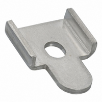
R99-11
Description
MOUNTING BRACKET FOR G3NA RELAY
Manufacturer
Omron
Series
G3NAr
Specifications of R99-11
Accessory Type
Mounting Bracket, Plate
Associated Relay Series
G3NA-240B, G3NA-440B(-2)
Termination Style
Screw
Mounting Style
Screw
Width
16 mm
For Use With/related Products
G3NA-240B and G3NA-440B
For Use With
Z2588 - RELAY SSR 40A 5VDCZ2587 - RELAY SSR 40A 230VACZ173 - RELAY SSR 40A@220VAC ZERO CROSSZ174 - RELAY SSR 40A@220VAC ZERO CROSSZ172 - RELAY SSR 40A@220VAC ZERO CROSS
Lead Free Status / RoHS Status
Lead free / RoHS Compliant
Color
-
Lead Free Status / Rohs Status
Lead free / RoHS Compliant
Other names
R99-11
R9911
R9911NC
Z2000
R9911
R9911NC
Z2000


Preventing Overheating with a
High-capacity Heat Sink (Y92B-P250NF)
• When the High-capacity Heat Sink is used, high-capacity switching
• If the Fan stops due to a power supply error, due to foreign matter
• A thermostat is provided to detect overheating. The thermostat
• Do not connect the thermostat directly to the load power supply.
• Terminals equivalent to Faston #187 are used for the thermostat
• Do not place heat-dissipating silicon grease on the thermostat.
• Do not solder the thermostat terminals.
• The following diagram shows a protective circuit example.
Ventilating a High-capacity Heat Sink
(Y92B-P250NF)
• Refer to Ventilation Outside the Control Panel.
Operating Conditions
• Do not apply currents exceeding the rated current otherwise, the
• As protection against accidents due to short-circuiting, be sure to
• Do not apply overvoltages to the input circuit or output circuit. Fail-
• Do not drop the G3NA or otherwise subject it to abnormal shock.
• Keep the cooling system running continuously during the ON/OFF
Noise Terminal Voltage
According to EN55011
The G3NA-UTU complies with EN55011 standards when a capacitor
is connected to the load power supply as shown in the following cir-
cuit diagram.
Coil
power
supply
Capacitor C1
0.1 µF
at 75 A or 90 A requires forced cooling with a fan. Connect the Fan
to a power supply according to its ratings specifications.
in the power supply connection, or due to aging, the Heat Sink will
heat to high temperatures, possibly resulting in failure of the SSR or
adverse affects on other devices. Implement an overheating pre-
vention measure, such as turning OFF the load current, if the Heat
Sink overheats.
uses a NC contact, i.e., the circuit will be opened for overheating.
This thermostat can be used to stop the operation of the SSR.
Implement an overheating prevention measure by using this signal
to output an alarm or perform another response applicable to the
system. Also, confirm that there is no problem with the overall sys-
tem.
Connect it to a contactor or other shutoff device connected above
the SSR.
terminals.
temperature of the G3NA may rise excessively.
install protective devices, such as fuses and no-fuse breakers, on
the power supply side.
ure or burning may result.
Malfunction or failure may result.
operation of the SSR. This is to allow residual heat to dissipate
while the SSR is OFF.
C1
Input side
3 m max.
Circuit breaker
(coil side)
Input
G3NA-UTU
type
(NC contact)
Thermostat
Output
Varistor
•
•
G3NA-2@@: 470 V, 0.6 W
G3NA-4@@: 910 V, 0.8 W
Y92B-P250NF
G3NA
Load
C2
Capacitor C2
•
•
G3NA-2@@: 1 µF, 250 VAC
G3NA-4@@: 0.5 µF, 500 VAC
Load side
Load
Circuit breaker
(contact side)
Circuit
breaker
• Connect capacitor C1 to both sides of the input terminals for a
• Connect capacitor C2 to both sides of the load power supply out-
• Connect the varistor to both sides of the G3NA output terminals.
• Do not use an input line that is longer than 3 m.
Loss Time
The loss time will increase when the G3NA is used at a low applied
voltage or current. Be sure that this does not cause any problems.
Using DC Loads
For a DC or L load, a diode should be connected in parallel the load
to absorb the counter electromotive force of the load.
Fuses
Connect a quick-break fuse in series with the load as a short-circuit
protection measure. Use one of the fuses in the following table or one
with equivalent or better characteristics.
Recommended Fuses
Reverse Connection
The output terminal side of the G3NA-D210B is connected to a built-
in diode to protect the SSR from damage that may result from
reverse connection. The SSR, however, cannot withstand one minute
or more if the wires are connected in reverse. Therefore, pay the
utmost attention not to make polarity mistakes on the load side.
Input
5 A
8 A
10 A
15 A
20 A
25 A
30 A
40 A
45 A
50 A
75 A
80 A
100 A
G3NA with a DC input.
put.
load current
G3NA rated
Loss time
SSR
60LFF5
60LFF8
60LFF10
60LFF15
60LFF20
50SHA20
60PFF25
50SHA25
60PFF30
50SHA30
50SHA40
50SHA45
50SHA50
50SHA75
50SHA80
50SHB100
Fuse model
Solid State Relay
Kyosan Electric
Manufacturing
Company
Manufacturer
Load
G3NA
Load power
supply
G3NA-205B
G3NA-210B
G3NA-220B
G3NA-240B
G3NA-275B-UTU
G3NA-290B-UTU
Applicable SSR
465
Related parts for R99-11
Image
Part Number
Description
Manufacturer
Datasheet
Request
R

Part Number:
Description:
1 Sheet Of 120 Plastic Labels
Manufacturer:
Omron
Datasheet:

Part Number:
Description:
MOUNTING BRACKET -G7J
Manufacturer:
Omron
Datasheet:
Part Number:
Description:
DUST COVER FOR G8P SERIES
Manufacturer:
Omron
Datasheet:

Part Number:
Description:
10 Sheets (484 Per)
Manufacturer:
Omron
Datasheet:

Part Number:
Description:
Mounting Bracket
Manufacturer:
Omron
Datasheet:

Part Number:
Description:
BRACKET FOR G7L
Manufacturer:
Omron
Datasheet:
Part Number:
Description:
Tool For P6DS Socket
Manufacturer:
Omron
Datasheet:
Part Number:
Description:
NAMEPLATE FOR MY
Manufacturer:
Omron
Datasheet:

Part Number:
Description:
G3NA MTG BRACKET
Manufacturer:
Omron
Datasheet:

Part Number:
Description:
G6S-2GLow Signal Relay
Manufacturer:
Omron Corporation
Datasheet:
Part Number:
Description:
Compact, Low-cost, SSR Switching 5 to 20 A
Manufacturer:
Omron Corporation
Datasheet:
Part Number:
Description:
Manufacturer:
Omron Corporation
Datasheet: