R99-11 Omron, R99-11 Datasheet - Page 6
R99-11
Manufacturer Part Number
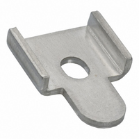
R99-11
Description
MOUNTING BRACKET FOR G3NA RELAY
Manufacturer
Omron
Series
G3NAr
Specifications of R99-11
Accessory Type
Mounting Bracket, Plate
Associated Relay Series
G3NA-240B, G3NA-440B(-2)
Termination Style
Screw
Mounting Style
Screw
Width
16 mm
For Use With/related Products
G3NA-240B and G3NA-440B
For Use With
Z2588 - RELAY SSR 40A 5VDCZ2587 - RELAY SSR 40A 230VACZ173 - RELAY SSR 40A@220VAC ZERO CROSSZ174 - RELAY SSR 40A@220VAC ZERO CROSSZ172 - RELAY SSR 40A@220VAC ZERO CROSS
Lead Free Status / RoHS Status
Lead free / RoHS Compliant
Color
-
Lead Free Status / Rohs Status
Lead free / RoHS Compliant
Other names
R99-11
R9911
R9911NC
Z2000
R9911
R9911NC
Z2000


One Cycle Surge Current
The values shown by the solid line are for non-repetitive inrush currents.
Keep the inrush current below the values shown by the dotted line if it occurs repetitively.
Thermal Resistance Rth
(Back of Junction SSR) (Examples)
456
Temperature
Characteristics (for
Must Operate Voltage
and Must Release
Voltage)
G3NA-205B
G3NA-210B
G3NA-220B
G3NA-240B
G3NA-275B-UTU
G3NA-475B-UTU
G3NA-290B-UTU
G3NA-490B-UTU
G3NA-D210B
−20
−40
60
40
20
30
28
26
24
22
20
18
16
14
12
10
40
20
0
8
6
4
2
0
0
−30
G3NA-205B
10
G3NA-D210B
10
G3NA-2❏❏B AC input
20
−20
30
30
50 70
50
0
100
100
Model
Solid State Relay
200 300
Ambient temperature (°C)
20
200
Energized time (ms)
Energized time (ms)
500
500
40
1,000
60
1,000
80
5,000
2,000
100
Heat Sink Area vs.
Load Current
G3NA
150
100
3,000
2,000
1,000
50
900
800
700
600
500
400
300
200
100
0
700
500
300
200
100
10
0
70
50
30
20
G3NA-210B
G3NA-410B
G3NA-275B-UTU
G3NA-475B-UTU
10
0
G3NA-220B
Ambient
temperature 80°C
2
30
Rth (°C/W)
4
50
30
6
3.22
2.62
1.99
0.45
0.45
2.62
100
8
50
10
200
12
100
Energized time (ms)
500
Energized time (ms)
14
Ambient
temperature 40°C
Aluminum plate
3.2 mm thick
16
1,000
Load current (A)
18
300
20
22
5,000
1,000
24
1,200
1,000
200
150
100
50
800
600
400
200
Note: The heat sink area refers to the combined area
0
Thermal Resistance Rth of Heat Sinks
(Examples)
Note: When using a commercially available heat sink, use one with a
10
Y92B-N50
Y92B-N100
Y92B-N150
Y92B-A100
Y92B-A150N
Y92B-A250
Y92B-P250NF
0
G3NA-220B
G3NA-420B
G3NA-290B-UTU
G3NA-490B-UTU
10
30
of the sides of the heat sink that radiate heat.
For example, when a current of 18 A is allowed
to flow through the SSR at 40°C, the graph
shows that the heat sink area is about 450 cm
Therefore, if the heat sink is square, one side of
the heat sink must be 15 cm (
longer.
thermal resistance equal to or less that the OMRON Heat Sink.
50
30
100
50
200
Model
100
500
Energized time (ms)
Energized time (ms)
1,000
300
5,000
1,000
400
300
200
100
0
10
G3NA-240B
G3NA-440B/-450B
450 (cm
30
50
100
2
Rth (°C/W)
)/2
200
1.63
1.38
1.63
1.37
1.00
0.46
) or
2.8
2
500
Energized time (ms)
.
1,000
5,000
Related parts for R99-11
Image
Part Number
Description
Manufacturer
Datasheet
Request
R

Part Number:
Description:
1 Sheet Of 120 Plastic Labels
Manufacturer:
Omron
Datasheet:

Part Number:
Description:
MOUNTING BRACKET -G7J
Manufacturer:
Omron
Datasheet:
Part Number:
Description:
DUST COVER FOR G8P SERIES
Manufacturer:
Omron
Datasheet:

Part Number:
Description:
10 Sheets (484 Per)
Manufacturer:
Omron
Datasheet:

Part Number:
Description:
Mounting Bracket
Manufacturer:
Omron
Datasheet:

Part Number:
Description:
BRACKET FOR G7L
Manufacturer:
Omron
Datasheet:
Part Number:
Description:
Tool For P6DS Socket
Manufacturer:
Omron
Datasheet:
Part Number:
Description:
NAMEPLATE FOR MY
Manufacturer:
Omron
Datasheet:

Part Number:
Description:
G3NA MTG BRACKET
Manufacturer:
Omron
Datasheet:

Part Number:
Description:
G6S-2GLow Signal Relay
Manufacturer:
Omron Corporation
Datasheet:
Part Number:
Description:
Compact, Low-cost, SSR Switching 5 to 20 A
Manufacturer:
Omron Corporation
Datasheet:
Part Number:
Description:
Manufacturer:
Omron Corporation
Datasheet: