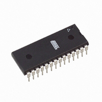
ATMEGA168-20PU Atmel, ATMEGA168-20PU Datasheet - Page 177

ATMEGA168-20PU
Manufacturer Part Number
ATMEGA168-20PU
Description
IC AVR MCU 16K 20MHZ 28DIP
Manufacturer
Atmel
Series
AVR® ATmegar
Datasheets
1.ATAVRTS2080B.pdf
(378 pages)
2.ATMEGA48-20AU.pdf
(35 pages)
3.ATMEGA88-20MU.pdf
(33 pages)
4.ATMEGA168-20AU.pdf
(359 pages)
Specifications of ATMEGA168-20PU
Core Processor
AVR
Core Size
8-Bit
Speed
20MHz
Connectivity
I²C, SPI, UART/USART
Peripherals
Brown-out Detect/Reset, POR, PWM, WDT
Number Of I /o
23
Program Memory Size
16KB (8K x 16)
Program Memory Type
FLASH
Eeprom Size
512 x 8
Ram Size
1K x 8
Voltage - Supply (vcc/vdd)
2.7 V ~ 5.5 V
Data Converters
A/D 6x10b
Oscillator Type
Internal
Operating Temperature
-40°C ~ 85°C
Package / Case
28-DIP (0.300", 7.62mm)
Processor Series
ATMEGA16x
Core
AVR8
Data Bus Width
8 bit
Data Ram Size
1 KB
Interface Type
2-Wire, SPI, USART, Serial
Maximum Clock Frequency
20 MHz
Number Of Programmable I/os
23
Number Of Timers
3
Operating Supply Voltage
2.7 V to 5.5 V
Maximum Operating Temperature
+ 85 C
Mounting Style
Through Hole
3rd Party Development Tools
EWAVR, EWAVR-BL
Development Tools By Supplier
ATAVRDRAGON, ATSTK500, ATSTK600, ATAVRISP2, ATAVRONEKIT
Minimum Operating Temperature
- 40 C
On-chip Adc
10 bit, 6 Channel
A/d Inputs
6-Channel, 10-Bit
Cpu Speed
20 MIPS
Eeprom Memory
512 Bytes
Input Output
23
Interface
I2C/SPI/UART/USART
Memory Type
Flash
Number Of Bits
8
Package Type
28-pin PDIP
Programmable Memory
16K Bytes
Timers
2-8-bit, 1-16-bit
Voltage, Range
4.5-5.5 V
Controller Family/series
AVR MEGA
No. Of I/o's
23
Eeprom Memory Size
512Byte
Ram Memory Size
1KB
Rohs Compliant
Yes
For Use With
ATSTK600-TQFP32 - STK600 SOCKET/ADAPTER 32-TQFPATSTK600 - DEV KIT FOR AVR/AVR32770-1007 - ISP 4PORT ATMEL AVR MCU SPI/JTAGATAVRDRAGON - KIT DRAGON 32KB FLASH MEM AVRATAVRISP2 - PROGRAMMER AVR IN SYSTEMATJTAGICE2 - AVR ON-CHIP D-BUG SYSTEM
Lead Free Status / RoHS Status
Lead free / RoHS Compliant
Available stocks
Company
Part Number
Manufacturer
Quantity
Price
Part Number:
ATMEGA168-20PU
Manufacturer:
ATMEL/爱特梅尔
Quantity:
20 000
- ATAVRTS2080B PDF datasheet
- ATMEGA48-20AU PDF datasheet #2
- ATMEGA88-20MU PDF datasheet #3
- ATMEGA168-20AU PDF datasheet #4
- Current page: 177 of 359
- Download datasheet (3Mb)
17.5.2
17.5.3
2545E–AVR–02/05
Sending Frames with 9 Data Bit
Transmitter Flags and Interrupts
If 9-bit characters are used (UCSZn = 7), the ninth bit must be written to the TXB8 bit in UCS-
RnB before the low byte of the character is written to UDRn. The following code examples show
a transmit function that handles 9-bit characters. For the assembly code, the data to be sent is
assumed to be stored in registers R17:R16.
Notes:
The ninth bit can be used for indicating an address frame when using multi processor communi-
cation mode or for other protocol handling as for example synchronization.
The USART Transmitter has two flags that indicate its state: USART Data Register Empty
(UDREn) and Transmit Complete (TXCn). Both flags can be used for generating interrupts.
The Data Register Empty (UDREn) Flag indicates whether the transmit buffer is ready to receive
new data. This bit is set when the transmit buffer is empty, and cleared when the transmit buffer
Assembly Code Example
C Code Example
USART_Transmit:
void USART_Transmit( unsigned int data )
{
}
; Wait for empty transmit buffer
sbis UCSRnA,UDREn
rjmp USART_Transmit
; Copy 9th bit from r17 to TXB8
cbi
sbrc r17,0
sbi
; Put LSB data (r16) into buffer, sends the data
out
ret
/* Wait for empty transmit buffer */
while ( !( UCSRnA & (1<<UDREn))) )
/* Copy 9th bit to TXB8 */
UCSRnB &= ~(1<<TXB8);
if ( data & 0x0100 )
/* Put data into buffer, sends the data */
UDRn = data;
1. These transmit functions are written to be general functions. They can be optimized if the con-
2.
UCSRnB |= (1<<TXB8);
See ”About Code Examples” on page 6.
tents of the UCSRnB is static. For example, only the TXB8 bit of the UCSRnB Register is used
after initialization.
For I/O Registers located in extended I/O map, “IN”, “OUT”, “SBIS”, “SBIC”, “CBI”, and “SBI”
instructions must be replaced with instructions that allow access to extended I/O. Typically
“LDS” and “STS” combined with “SBRS”, “SBRC”, “SBR”, and “CBR”.
UCSRnB,TXB8
UCSRnB,TXB8
UDRn,r16
;
(1)(2)
(1)(2)
ATmega48/88/168
177
Related parts for ATMEGA168-20PU
Image
Part Number
Description
Manufacturer
Datasheet
Request
R

Part Number:
Description:
Manufacturer:
Atmel Corporation
Datasheet:

Part Number:
Description:
Manufacturer:
Atmel Corporation
Datasheet:

Part Number:
Description:
Manufacturer:
ATMEL Corporation
Datasheet:

Part Number:
Description:
IC AVR MCU 16K 20MHZ 32TQFP
Manufacturer:
Atmel
Datasheet:

Part Number:
Description:
IC AVR MCU 16K 20MHZ 32-QFN
Manufacturer:
Atmel
Datasheet:

Part Number:
Description:
MCU AVR 16K FLASH 15MHZ 32-TQFP
Manufacturer:
Atmel
Datasheet:

Part Number:
Description:
MCU AVR 16K FLASH 15MHZ 32-QFN
Manufacturer:
Atmel
Datasheet:

Part Number:
Description:
IC AVR MCU 16K 20MHZ 32TQFP
Manufacturer:
Atmel
Datasheet:

Part Number:
Description:
MCU AVR 16KB FLASH 20MHZ 32QFN
Manufacturer:
Atmel
Datasheet:

Part Number:
Description:
MCU AVR 16KB FLASH 20MHZ 32TQFP
Manufacturer:
Atmel
Datasheet:

Part Number:
Description:
IC MCU AVR 16K FLASH 32-QFN
Manufacturer:
Atmel
Datasheet:


