PIC16C771/JW Microchip Technology, PIC16C771/JW Datasheet - Page 23
PIC16C771/JW
Manufacturer Part Number
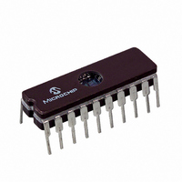
PIC16C771/JW
Description
IC MCU EPROM4KX14 A/D PWM 20CDIP
Manufacturer
Microchip Technology
Series
PIC® 16Cr
Datasheets
1.PIC16C770-ISO.pdf
(220 pages)
2.PIC16C770-ISO.pdf
(6 pages)
3.PIC16C770-ISO.pdf
(8 pages)
Specifications of PIC16C771/JW
Core Processor
PIC
Core Size
8-Bit
Speed
20MHz
Connectivity
I²C, SPI
Peripherals
Brown-out Detect/Reset, POR, PWM, WDT
Number Of I /o
15
Program Memory Size
7KB (4K x 14)
Program Memory Type
EPROM, UV
Ram Size
256 x 8
Voltage - Supply (vcc/vdd)
4 V ~ 5.5 V
Data Converters
A/D 6x12b
Oscillator Type
External
Operating Temperature
0°C ~ 70°C
Package / Case
20-CDIP (0.300", 7.62mm) Window
For Use With
ISPICR1 - ADAPTER IN-CIRCUIT PROGRAMMINGDVA16XP200 - ADAPTER ICE 20DIP/SOIC/SSOPAC164028 - MODULE SKT PROMATEII 20SOIC/DIP
Lead Free Status / RoHS Status
Contains lead / RoHS non-compliant
Eeprom Size
-
Other names
Q1066306


2.2.2.8
The Power Control (PCON) register contains a flag bit
to allow differentiation between a Power-on Reset
(POR) to an external MCLR Reset or WDT Reset.
Those devices with brown-out detection circuitry con-
tain an additional bit to differentiate a Brown-out Reset
condition from a Power-on Reset condition.
The PCON register also contains the frequency select
bit of the INTRC or ER oscillator.
REGISTER 2-8:
2002 Microchip Technology Inc.
bit 7-4
bit 3
bit 2
bit 1
bit 0
PCON REGISTER
POWER CONTROL REGISTER (PCON: 8Eh)
Unimplemented: Read as '0'
OSCF: Oscillator Speed bit
INTRC Mode
1 = 4 MHz nominal
0 = 37 kHz nominal
ER Mode
1 = Oscillator frequency depends on the external resistor value on the OSC1 pin.
0 = 37 kHz nominal
All other modes
x = Ignored
Unimplemented: Read as '0'
POR: Power-on Reset Status bit
1 = No Power-on Reset occurred
0 = A Power-on Reset occurred (must be set in software after a Power-on Reset occurs)
BOR: Brown-out Reset Status bit (See Section 2.2.2.8 Note)
1 = No Brown-out Reset occurred
0 = A Brown-out Reset occurred (must be set in software after a Brown-out Reset occurs)
bit 7
Legend:
R = Readable bit
- n = Value at POR
U-0
—
U-0
—
U-0
—
W = Writable bit
’1’ = Bit is set
U-0
—
Note:
PIC16C717/770/771
R/W-1
OSCF
q = Value depends on conditions
U = Unimplemented bit, read as ‘0’
’0’ = Bit is cleared
BOR is unknown on Power-on Reset. It
must then be set by the user and checked
on subsequent RESETS to see if BOR is
clear, indicating a brown-out has occurred.
The BOR status bit is a don’t care and is
not necessarily predictable if the brown-out
circuit is disabled (by clearing the BODEN
bit in the Configuration word).
U-0
—
x = Bit is unknown
R/W-q
POR
DS41120B-page 21
R/W-q
BOR
bit 0
Related parts for PIC16C771/JW
Image
Part Number
Description
Manufacturer
Datasheet
Request
R

Part Number:
Description:
IC MCU OTP 8KX14 A/D PWM 44PLCC
Manufacturer:
Microchip Technology
Datasheet:
Part Number:
Description:
IC MCU OTP 8KX14 A/D PWM 44PLCC
Manufacturer:
Microchip Technology
Datasheet:

Part Number:
Description:
IC MCU OTP 8KX14 A/D PWM 44TQFP
Manufacturer:
Microchip Technology
Datasheet:

Part Number:
Description:
IC MCU OTP 8KX14 A/D PWM 44-MQFP
Manufacturer:
Microchip Technology
Datasheet:

Part Number:
Description:
IC MCU OTP 8KX14 A/D PWM 40DIP
Manufacturer:
Microchip Technology
Datasheet:
Part Number:
Description:
IC MCU OTP 8KX14 A/D PWM 44PLCC
Manufacturer:
Microchip Technology
Datasheet:
Part Number:
Description:
IC MCU OTP 8KX14 A/D PWM 40DIP
Manufacturer:
Microchip Technology
Datasheet:
Part Number:
Description:
IC MCU OTP 8KX14 A/D PWM 40DIP
Manufacturer:
Microchip Technology
Datasheet:
Part Number:
Description:
IC MCU OTP 8KX14 A/D PWM 40DIP
Manufacturer:
Microchip Technology
Datasheet:
Part Number:
Description:
IC MCU OTP 8KX14 A/D PWM 44PLCC
Manufacturer:
Microchip Technology
Datasheet:
Part Number:
Description:
IC MCU OTP 8KX14 A/D PWM 44PLCC
Manufacturer:
Microchip Technology
Datasheet:
Part Number:
Description:
IC MCU OTP 8KX14 A/D PWM 44-MQFP
Manufacturer:
Microchip Technology
Datasheet:
Part Number:
Description:
IC MCU OTP 8KX14 A/D PWM 40DIP
Manufacturer:
Microchip Technology
Datasheet:
Part Number:
Description:
IC MCU OTP 8KX14 A/D PWM 44-MQFP
Manufacturer:
Microchip Technology
Datasheet:
Part Number:
Description:
IC MCU OTP 8KX14 A/D PWM 40DIP
Manufacturer:
Microchip Technology
Datasheet: