PIC16C771/JW Microchip Technology, PIC16C771/JW Datasheet - Page 64
PIC16C771/JW
Manufacturer Part Number
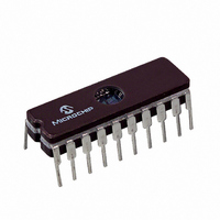
PIC16C771/JW
Description
IC MCU EPROM4KX14 A/D PWM 20CDIP
Manufacturer
Microchip Technology
Series
PIC® 16Cr
Datasheets
1.PIC16C770-ISO.pdf
(220 pages)
2.PIC16C770-ISO.pdf
(6 pages)
3.PIC16C770-ISO.pdf
(8 pages)
Specifications of PIC16C771/JW
Core Processor
PIC
Core Size
8-Bit
Speed
20MHz
Connectivity
I²C, SPI
Peripherals
Brown-out Detect/Reset, POR, PWM, WDT
Number Of I /o
15
Program Memory Size
7KB (4K x 14)
Program Memory Type
EPROM, UV
Ram Size
256 x 8
Voltage - Supply (vcc/vdd)
4 V ~ 5.5 V
Data Converters
A/D 6x12b
Oscillator Type
External
Operating Temperature
0°C ~ 70°C
Package / Case
20-CDIP (0.300", 7.62mm) Window
For Use With
ISPICR1 - ADAPTER IN-CIRCUIT PROGRAMMINGDVA16XP200 - ADAPTER ICE 20DIP/SOIC/SSOPAC164028 - MODULE SKT PROMATEII 20SOIC/DIP
Lead Free Status / RoHS Status
Contains lead / RoHS non-compliant
Eeprom Size
-
Other names
Q1066306


PIC16C717/770/771
8.3.5
In half-bridge or full-bridge applications, driven by half-
bridge outputs (see Figure 8-7), the power switches
normally require longer time to turn off than to turn on.
If both the upper and lower power switches are
switched at the same time (one turned on, and the
other turned off), both switches will be on for a short
period of time, until one switch completely turns off.
During this time, a very high current, called shoot-
through current, will flow through both power switches,
REGISTER 8-2:
8.3.6
In the Full-Bridge Output mode, the PWM1M1 bit in the
CCP1CON register allows user to control the Forward/
Reverse direction. When the application firmware
changes this direction control bit, the ECCP module will
assume the new direction on the next PWM cycle. The
current PWM cycle still continues, however, the non-
FIGURE 8-10: PWM DIRECTION CHANGE
DS41120B-page 62
Note 1:
2:
SIGNAL
P1A (Active High)
P1B (Active High)
P1C (Active High)
P1D (Active High)
bit 7-0
PROGRAMMABLE DEADBAND
DELAY
DIRECTION CHANGE IN FULL-
BRIDGE OUTPUT MODE
The Direction bit in the ECCP Control Register (CCP1CON<PWM1M1>) is written anytime during the PWM cycle.
The P1A and P1C signals switch T
changing direction. The modulated P1B and P1D signals are inactive at this time.
PWM DELAY REGISTER (P1DEL: 97H)
bit 7
P1DEL<7:0>: PWM Delay Count for Half-Bridge Output Mode: Number of F
cycles between the P1A transition and the P1B transition.
Legend:
R = Readable bit
- n = Value at POR
P1DEL7
R/W-0
DC
P1DEL6
R/W-0
OSC
PERIOD
, 4*Tosc or 16*T
(1)
P1DEL5
R/W-0
W = Writable bit
’1’ = Bit is set
P1DEL4
OSC
R/W-0
shorting the bridge supply. To avoid this potentially
destructive shoot-through current from flowing during
switching, turning on the power switch is normally
delayed to allow the other switch to completely turn off.
In the Half-Bridge Output mode, a digitally program-
mable deadband delay is available to avoid shoot-
through current from destroying the bridge power
switches. The delay occurs at the signal transition from
the non-active state to the active state. See Figure 8-6
for illustration. The P1DEL register sets the amount of
delay.
modulated outputs, P1A and P1C signals, will transition
to the new direction TOSC, 4 TOSC or 16 TOSC (for
Timer2 prescale T2CKRS<1:0> = 00, 01 and 1x
respectively) earlier, before the end of the period. Dur-
ing this transition cycle, the modulated outputs, P1B
and P1D, will go to the inactive state. See Figure 8-10
for illustration.
, depending on the Timer2 prescaler value, earlier when
P1DEL3
R/W-0
U = Unimplemented bit, read as ‘0’
’0’ = Bit is cleared
(2)
PERIOD
P1DEL2
R/W-0
2002 Microchip Technology Inc.
x = Bit is unknown
P1DEL1
R/W-0
OSC
/4 (Tosc 4)
P1DEL0
R/W-0
bit 0
Related parts for PIC16C771/JW
Image
Part Number
Description
Manufacturer
Datasheet
Request
R

Part Number:
Description:
IC MCU OTP 8KX14 A/D PWM 44PLCC
Manufacturer:
Microchip Technology
Datasheet:
Part Number:
Description:
IC MCU OTP 8KX14 A/D PWM 44PLCC
Manufacturer:
Microchip Technology
Datasheet:

Part Number:
Description:
IC MCU OTP 8KX14 A/D PWM 44TQFP
Manufacturer:
Microchip Technology
Datasheet:

Part Number:
Description:
IC MCU OTP 8KX14 A/D PWM 44-MQFP
Manufacturer:
Microchip Technology
Datasheet:

Part Number:
Description:
IC MCU OTP 8KX14 A/D PWM 40DIP
Manufacturer:
Microchip Technology
Datasheet:
Part Number:
Description:
IC MCU OTP 8KX14 A/D PWM 44PLCC
Manufacturer:
Microchip Technology
Datasheet:
Part Number:
Description:
IC MCU OTP 8KX14 A/D PWM 40DIP
Manufacturer:
Microchip Technology
Datasheet:
Part Number:
Description:
IC MCU OTP 8KX14 A/D PWM 40DIP
Manufacturer:
Microchip Technology
Datasheet:
Part Number:
Description:
IC MCU OTP 8KX14 A/D PWM 40DIP
Manufacturer:
Microchip Technology
Datasheet:
Part Number:
Description:
IC MCU OTP 8KX14 A/D PWM 44PLCC
Manufacturer:
Microchip Technology
Datasheet:
Part Number:
Description:
IC MCU OTP 8KX14 A/D PWM 44PLCC
Manufacturer:
Microchip Technology
Datasheet:
Part Number:
Description:
IC MCU OTP 8KX14 A/D PWM 44-MQFP
Manufacturer:
Microchip Technology
Datasheet:
Part Number:
Description:
IC MCU OTP 8KX14 A/D PWM 40DIP
Manufacturer:
Microchip Technology
Datasheet:
Part Number:
Description:
IC MCU OTP 8KX14 A/D PWM 44-MQFP
Manufacturer:
Microchip Technology
Datasheet:
Part Number:
Description:
IC MCU OTP 8KX14 A/D PWM 40DIP
Manufacturer:
Microchip Technology
Datasheet: