PIC16C771/JW Microchip Technology, PIC16C771/JW Datasheet - Page 89
PIC16C771/JW
Manufacturer Part Number
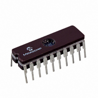
PIC16C771/JW
Description
IC MCU EPROM4KX14 A/D PWM 20CDIP
Manufacturer
Microchip Technology
Series
PIC® 16Cr
Datasheets
1.PIC16C770-ISO.pdf
(220 pages)
2.PIC16C770-ISO.pdf
(6 pages)
3.PIC16C770-ISO.pdf
(8 pages)
Specifications of PIC16C771/JW
Core Processor
PIC
Core Size
8-Bit
Speed
20MHz
Connectivity
I²C, SPI
Peripherals
Brown-out Detect/Reset, POR, PWM, WDT
Number Of I /o
15
Program Memory Size
7KB (4K x 14)
Program Memory Type
EPROM, UV
Ram Size
256 x 8
Voltage - Supply (vcc/vdd)
4 V ~ 5.5 V
Data Converters
A/D 6x12b
Oscillator Type
External
Operating Temperature
0°C ~ 70°C
Package / Case
20-CDIP (0.300", 7.62mm) Window
For Use With
ISPICR1 - ADAPTER IN-CIRCUIT PROGRAMMINGDVA16XP200 - ADAPTER ICE 20DIP/SOIC/SSOPAC164028 - MODULE SKT PROMATEII 20SOIC/DIP
Lead Free Status / RoHS Status
Contains lead / RoHS non-compliant
Eeprom Size
-
Other names
Q1066306


9.2.12
In Master-transmitter mode, serial data is output
through SDA, while SCL outputs the serial clock. The
first byte transmitted contains seven bits of address
data and the Read/Write (R/W) bit. In this case, the R/
W bit will be logic ’0’. Subsequent serial data is trans-
mitted eight bits at a time. After each byte is transmit-
ted, an Acknowledge bit is received. START and STOP
conditions are output to indicate the beginning and the
end of a serial transfer.
Transmission of a data byte, a 7-bit address, or either
half of a 10-bit address is accomplished by simply writ-
ing a value to the SSPBUF register. This action will set
the buffer full flag (BF) and allow the baud rate genera-
tor to begin counting and start the next transmission.
Each bit of address/data will be shifted out onto the
SDA pin after the falling edge of SCL is asserted (see
data hold time spec). SCL is held low for one baud rate
generator roll over count (T
before SCL is released high (see data setup time
spec). When the SCL pin is released high, it is held that
way for T
ble for that duration and some hold time after the next
falling edge of SCL. After the eighth bit is shifted out
(the falling edge of the eighth clock), the BF flag is
cleared and the master releases SDA. This allows the
slave device being addressed to respond with an ACK
bit during the ninth bit time. The status of ACK is read
into the ACKDT on the rising edge of the ninth clock. If
the master receives an Acknowledge, the Acknowl-
edge status bit (ACKSTAT) is cleared. Otherwise, the
bit is set. The SSPIF is set on the falling edge of the
ninth clock, and the master clock (baud rate generator)
is suspended until the next data byte is loaded into the
SSPBUF leaving SCL low and SDA unchanged
(Figure 9-18).
2002 Microchip Technology Inc.
BRG
I
TRANSMISSION
2
, the data on the SDA pin must remain sta-
C MASTER MODE
BRG
). Data should be valid
Advance Information
A typical transmit sequence would go as follows:
a)
b)
c)
d)
e)
f)
g)
h)
i)
j)
k)
l)
9.2.12.1
In Transmit mode, the BF bit (SSPSTAT<0>) is set
when the CPU writes to SSPBUF and is cleared when
all eight bits are shifted out.
9.2.12.2
If the user writes the SSPBUF when a transmit is
already in progress (i.e. SSPSR is still shifting out a
data byte), then WCOL is set and the contents of the
buffer are unchanged (the write doesn’t occur).
WCOL must be cleared in software.
9.2.12.3
In Transmit mode, the ACKSTAT bit (SSPCON2<6>) is
cleared when the slave has sent an Acknowledge
(ACK = 0), and is set when the slave does not Acknowl-
edge (ACK = 1). A slave sends an Acknowledge when
it has recognized its address (including a general call),
or when the slave has properly received its data.
PIC16C717/770/771
The user generates a START Condition by set-
ting the START enable bit (SEN) in SSPCON2.
SSPIF is set at the completion of the START
sequence.
The user resets the SSPIF bit and loads the
SSPBUF with seven bits of address plus R/W bit
to transmit.
Address and R/W is shifted out the SDA pin until
all eight bits are transmitted.
The MSSP Module shifts in the ACK bit from the
slave device, and writes its value into the
SSPCON2 register (SSPCON2<6>).
The module generates an interrupt at the end of
the ninth clock cycle by setting SSPIF.
The user resets the SSPIF bit and loads the
SSPBUF with eight bits of data.
DATA is shifted out the SDA pin until all eight bits
are transmitted.
The MSSP Module shifts in the ACK bit from the
slave device and writes its value into the
SSPCON2 register (SSPCON2<6>).
The MSSP module generates an interrupt at the
end of the ninth clock cycle by setting the SSPIF
bit.
The user resets the SSPIF bit and generates a
STOP condition by setting the STOP enable bit
PEN in SSPCON2.
SSPIF is set when the STOP condition is complete.
BF STATUS FLAG
WCOL STATUS FLAG
ACKSTAT STATUS FLAG
DS41120B-page 87
Related parts for PIC16C771/JW
Image
Part Number
Description
Manufacturer
Datasheet
Request
R

Part Number:
Description:
IC MCU OTP 8KX14 A/D PWM 44PLCC
Manufacturer:
Microchip Technology
Datasheet:
Part Number:
Description:
IC MCU OTP 8KX14 A/D PWM 44PLCC
Manufacturer:
Microchip Technology
Datasheet:

Part Number:
Description:
IC MCU OTP 8KX14 A/D PWM 44TQFP
Manufacturer:
Microchip Technology
Datasheet:

Part Number:
Description:
IC MCU OTP 8KX14 A/D PWM 44-MQFP
Manufacturer:
Microchip Technology
Datasheet:

Part Number:
Description:
IC MCU OTP 8KX14 A/D PWM 40DIP
Manufacturer:
Microchip Technology
Datasheet:
Part Number:
Description:
IC MCU OTP 8KX14 A/D PWM 44PLCC
Manufacturer:
Microchip Technology
Datasheet:
Part Number:
Description:
IC MCU OTP 8KX14 A/D PWM 40DIP
Manufacturer:
Microchip Technology
Datasheet:
Part Number:
Description:
IC MCU OTP 8KX14 A/D PWM 40DIP
Manufacturer:
Microchip Technology
Datasheet:
Part Number:
Description:
IC MCU OTP 8KX14 A/D PWM 40DIP
Manufacturer:
Microchip Technology
Datasheet:
Part Number:
Description:
IC MCU OTP 8KX14 A/D PWM 44PLCC
Manufacturer:
Microchip Technology
Datasheet:
Part Number:
Description:
IC MCU OTP 8KX14 A/D PWM 44PLCC
Manufacturer:
Microchip Technology
Datasheet:
Part Number:
Description:
IC MCU OTP 8KX14 A/D PWM 44-MQFP
Manufacturer:
Microchip Technology
Datasheet:
Part Number:
Description:
IC MCU OTP 8KX14 A/D PWM 40DIP
Manufacturer:
Microchip Technology
Datasheet:
Part Number:
Description:
IC MCU OTP 8KX14 A/D PWM 44-MQFP
Manufacturer:
Microchip Technology
Datasheet:
Part Number:
Description:
IC MCU OTP 8KX14 A/D PWM 40DIP
Manufacturer:
Microchip Technology
Datasheet: