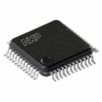
LPC2103FBD48,151 NXP Semiconductors, LPC2103FBD48,151 Datasheet - Page 16

LPC2103FBD48,151
Manufacturer Part Number
LPC2103FBD48,151
Description
IC ARM7 MCU FLASH 32K 48-LQFP
Manufacturer
NXP Semiconductors
Series
LPC2100r
Datasheet
1.LPC2101FBD48151.pdf
(37 pages)
Specifications of LPC2103FBD48,151
Program Memory Type
FLASH
Program Memory Size
32KB (32K x 8)
Package / Case
48-LQFP
Core Processor
ARM7
Core Size
16/32-Bit
Speed
70MHz
Connectivity
I²C, Microwire, SPI, SSI, SSP, UART/USART
Peripherals
POR, PWM, WDT
Number Of I /o
32
Ram Size
8K x 8
Voltage - Supply (vcc/vdd)
1.65 V ~ 3.6 V
Data Converters
A/D 8x10b
Oscillator Type
Internal
Operating Temperature
-40°C ~ 85°C
Processor Series
LPC21
Core
ARM7TDMI-S
Data Bus Width
16 bit, 32 bit
Data Ram Size
8 KB
Interface Type
I2C/JTAG/SPI/SSP/UART
Maximum Clock Frequency
70 MHz
Number Of Programmable I/os
32
Number Of Timers
4
Operating Supply Voltage
3.3 V
Maximum Operating Temperature
+ 85 C
Mounting Style
SMD/SMT
3rd Party Development Tools
MDK-ARM, RL-ARM, ULINK2, DB-LQFP48-LPC2103, MCB2103, MCB2103U, MCB2103UME, KSK-LPC2103-01, KSK-LPC2103-01PL, KSK-LPC2103-02
Development Tools By Supplier
OM10079, OM10081, OM10090
Minimum Operating Temperature
- 40 C
On-chip Adc
8-ch x 10-bit
Cpu Family
LPC2000
Device Core
ARM7TDMI-S
Device Core Size
16/32Bit
Frequency (max)
70MHz
Total Internal Ram Size
8KB
# I/os (max)
32
Number Of Timers - General Purpose
4
Operating Supply Voltage (typ)
1.8/3.3V
Operating Supply Voltage (max)
1.95/3.6V
Operating Supply Voltage (min)
1.65/3V
Instruction Set Architecture
RISC
Operating Temp Range
-40C to 85C
Operating Temperature Classification
Industrial
Mounting
Surface Mount
Pin Count
48
Package Type
LQFP
Lead Free Status / RoHS Status
Lead free / RoHS Compliant
For Use With
568-4310 - EVAL BOARD LPC2158 W/LCD568-4302 - BOARD EVAL LPC210X KS2103 JLINK568-4301 - BOARD EVAL LPC210X KS2103568-4300 - BOARD EVAL LPC210X MCB2103568-4297 - BOARD EVAL LPC21XX MCB2100MCB2103UME - BOARD EVAL MCB2103 + ULINK-MEMCB2103U - BOARD EVAL MCB2103 + ULINK2622-1013 - BOARD FOR LPC2103 48-LQFP622-1008 - BOARD FOR LPC9103 10-HVSONMCB2103 - BOARD EVAL NXP LPC2101/2101/2103622-1005 - USB IN-CIRCUIT PROG ARM7 LPC2K
Eeprom Size
-
Lead Free Status / Rohs Status
Compliant
Other names
568-2094
935280966151
LPC2103FBD48-S
935280966151
LPC2103FBD48-S
Available stocks
Company
Part Number
Manufacturer
Quantity
Price
Company:
Part Number:
LPC2103FBD48,151
Manufacturer:
NXP Semiconductors
Quantity:
10 000
NXP Semiconductors
LPC2101_02_03_4
Product data sheet
6.14.1 Features
6.15.1 Features
6.14 General purpose 16-bit timers/external event counters
6.15 Watchdog timer
The Timer/Counter is designed to count cycles of the peripheral clock (PCLK) or an
externally supplied clock and optionally generate interrupts or perform other actions at
specified timer values, based on four match registers. It also includes three capture inputs
to trap the timer value when an input signal transitions, optionally generating an interrupt.
Multiple pins can be selected to perform a single capture or match function, providing an
application with ‘or’ and ‘and’, as well as ‘broadcast’ functions among them.
The LPC2101/02/03 can count external events on one of the capture inputs if the
minimum external pulse is equal or longer than a period of the PCLK. In this configuration,
unused capture lines can be selected as regular timer capture inputs or used as external
interrupts.
The purpose of the watchdog is to reset the microcontroller within a reasonable amount of
time if it enters an erroneous state. When enabled, the watchdog will generate a system
reset if the user program fails to ‘feed’ (or reload) the watchdog within a predetermined
amount of time.
•
•
•
•
•
•
•
•
– Set HIGH on match.
– Toggle on match.
– Do nothing on match.
Two 16-bit timer/counters with a programmable 16-bit prescaler.
External event counter or timer operation.
Three 16-bit capture channels that can take a snapshot of the timer value when an
input signal transitions. A capture event may also optionally generate an interrupt.
Four 16-bit match registers that allow:
– Continuous operation with optional interrupt generation on match.
– Stop timer on match with optional interrupt generation.
– Reset timer on match with optional interrupt generation.
Four external outputs per timer/counter corresponding to match registers, with the
following capabilities:
– Set LOW on match.
– Set HIGH on match.
– Toggle on match.
– Do nothing on match.
Internally resets chip if not periodically reloaded.
Debug mode.
Enabled by software but requires a hardware reset or a watchdog reset/interrupt to be
disabled.
Rev. 04 — 2 June 2009
Single-chip 16-bit/32-bit microcontrollers
LPC2101/02/03
© NXP B.V. 2009. All rights reserved.
16 of 37


