MAXQ2000-RAX+ Maxim Integrated Products, MAXQ2000-RAX+ Datasheet - Page 27
MAXQ2000-RAX+
Manufacturer Part Number
MAXQ2000-RAX+
Description
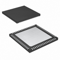
IC MCU 32K FLASH 68-QFN
Manufacturer
Maxim Integrated Products
Series
MAXQ™r
Datasheet
1.MAXQ2000-RAX.pdf
(39 pages)
Specifications of MAXQ2000-RAX+
Core Processor
RISC
Core Size
16-Bit
Speed
20MHz
Connectivity
1-Wire, SPI, UART/USART
Peripherals
LCD, POR, PWM, WDT
Number Of I /o
50
Program Memory Size
64KB (32K x 16)
Program Memory Type
FLASH
Ram Size
2K x 8
Voltage - Supply (vcc/vdd)
1.8 V ~ 2.75 V
Oscillator Type
Internal
Operating Temperature
-40°C ~ 85°C
Package / Case
68-QFN Exposed Pad
Processor Series
MAXQ
Core
RISC
Data Bus Width
16 bit
Data Ram Size
2 KB
Interface Type
JTAG, SPI
Maximum Clock Frequency
20 MHz
Number Of Programmable I/os
55
Number Of Timers
3
Operating Supply Voltage
2.5 V
Maximum Operating Temperature
+ 85 C
Mounting Style
SMD/SMT
Minimum Operating Temperature
- 40 C
Controller Family/series
MAXQ
No. Of I/o's
50
Ram Memory Size
2048Byte
Cpu Speed
20MHz
No. Of Timers
3
Embedded Interface Type
SPI, UART
Rohs Compliant
Yes
Development Tools By Supplier
MAXQ2000-KIT
Lead Free Status / RoHS Status
Lead free / RoHS Compliant
Eeprom Size
-
Data Converters
-
Lead Free Status / Rohs Status
Lead free / RoHS Compliant


Advanced power-management features minimize
power consumption by dynamically matching the pro-
cessing speed of the device to the required perfor-
mance level. This means device operation can be
slowed and power consumption minimized during peri-
ods of reduced activity. When more processing power
is required, the microcontroller can increase its operat-
ing frequency. Software-selectable clock-divide opera-
tions allow flexibility, selecting whether a system clock
cycle is 1, 2, 4, or 8 oscillator cycles. By performing this
function in software, a lower power state can be
entered without the cost of additional hardware.
For extremely power-sensitive applications, three addi-
tional low-power modes are available:
• PMM1: divide-by-256 power-management mode
• PMM2: 32kHz power-management mode (PMME = 1,
• Stop mode (STOP = 1)
In PMM1, one system clock is 256 oscillator cycles, sig-
nificantly reducing power consumption while the micro-
controller functions at reduced speed. In PMM2, the
device can run even slower by using the 32kHz oscilla-
tor as the clock source. The optional switchback fea-
ture allows enabled interrupt sources including external
interrupts, UARTs, and the SPI module to quickly exit
the power-management modes and return to a faster
internal clock rate.
Power consumption reaches its minimum in Stop mode.
In this mode, the external oscillator, system clock, and all
processing activity is halted. Stop mode is exited when
an enabled external interrupt pin is triggered, an external
reset signal is applied to the RESET pin, or the RTC time-
of-day alarm is activated. Upon exiting Stop mode, the
microcontroller can choose to wait for the external high-
frequency crystal to complete its warmup period, or it
can start execution immediately from its internal ring
oscillator while the warmup period completes.
Multiple interrupt sources are available for quick
response to internal and external events. The MAXQ
architecture uses a single interrupt vector (IV), single
interrupt-service routine (ISR) design. For maximum
flexibility, interrupts can be enabled globally, individual-
ly, or by module. When an interrupt condition occurs,
its individual flag is set, even if the interrupt source is
disabled at the local, module, or global level. Interrupt
flags must be cleared within the user-interrupt routine
(PMME = 1, CD1:0 = 00b)
CD1:0 = 11b)
Power Management
____________________________________________________________________
Interrupts
Low-Power LCD Microcontroller
to avoid repeated interrupts from the same source.
Application software must ensure a delay between the
write to the flag and the RETI instruction to allow time
for the interrupt hardware to remove the internal inter-
rupt condition. Asynchronous interrupt flags require a
one-instruction delay and synchronous interrupt flags
require a two-instruction delay.
When an enabled interrupt is detected, software jumps
to a user-programmable interrupt vector location. The
IV register defaults to 0000h on reset or power-up, so if
it is not changed to a different address, the user pro-
gram must determine whether a jump to 0000h came
from a reset or interrupt source.
Once software control has been transferred to the ISR,
the interrupt identification register (IIR) can be used to
determine if a system register or peripheral register
was the source of the interrupt. The specified module
can then be interrogated for the specific interrupt
source and software can take appropriate action.
Because the interrupts are evaluated by user software,
the user can define a unique interrupt priority scheme
for each application. The following interrupt sources are
available. Sources marked with an asterisk are not
available on the 56-pin version.
• Watchdog Interrupt
• External Interrupts 0 to 15 (INT10*, INT11*)
• RTC Time-of-Day and Subsecond Alarms
• Serial Port 0 Receive and Transmit Interrupts
• Serial Port 1 Receive and Transmit Interrupts*
• SPI Mode Fault, Write Collision, Receive Overrun, and
• Timer 0 Low Compare, Low Overflow,
• Timer 1 Low Compare, Low Overflow,
• Timer 2 Low Compare, Low Overflow,
• 1-Wire Presence Detect, Transmit Buffer Empty,
Several reset sources are provided for microcontroller
control. Although code execution is halted in the reset
state, the high-frequency oscillator and the ring oscillator
continue to oscillate. Internal resets such as the power-
on and watchdog resets assert the RESET pin low.
Transfer Complete Interrupts
Capture/Compare, and Overflow Interrupts
Capture/Compare, and Overflow Interrupts
Capture/Compare, and Overflow Interrupts
Transmit Shift Register Empty, Receive Buffer Full,
and Shift Register Full, Short, and Low Interrupts*
Reset Sources
27
Related parts for MAXQ2000-RAX+
Image
Part Number
Description
Manufacturer
Datasheet
Request
R

Part Number:
Description:
Microcontrollers (MCU) Low-Power LCD MCU
Manufacturer:
Maxim Integrated Products
Datasheet:
Part Number:
Description:
Microcontrollers (MCU) Low-Power LCD MCU
Manufacturer:
Maxim Integrated Products
Datasheet:
Part Number:
Description:
Microcontrollers (MCU) Low-Power LCD MCU
Manufacturer:
Maxim Integrated Products
Datasheet:
Part Number:
Description:
Microcontrollers (MCU) Low-Power LCD MCU
Manufacturer:
Maxim Integrated Products
Datasheet:
Part Number:
Description:
Microcontrollers (MCU) Low-Power LCD MCU
Manufacturer:
Maxim Integrated Products
Datasheet:

Part Number:
Description:
IC MCU 16BIT 32K FLASH 56-TQFN
Manufacturer:
Maxim Integrated Products
Datasheet:

Part Number:
Description:
IC MCU 16BIT 32K FLASH 68-QFN
Manufacturer:
Maxim Integrated Products
Datasheet:
Part Number:
Description:
IC MCU 32K FLASH 56-TQFN
Manufacturer:
Maxim Integrated Products
Datasheet:

Part Number:
Description:
IC MCU 32K FLASH 100-LQFP
Manufacturer:
Maxim Integrated Products
Datasheet:

Part Number:
Description:
EVAL KIT FOR MAXQ2000
Manufacturer:
Maxim Integrated Products
Datasheet:
Part Number:
Description:
MAX7528KCWPMaxim Integrated Products [CMOS Dual 8-Bit Buffered Multiplying DACs]
Manufacturer:
Maxim Integrated Products
Datasheet:
Part Number:
Description:
Single +5V, fully integrated, 1.25Gbps laser diode driver.
Manufacturer:
Maxim Integrated Products
Datasheet:
Part Number:
Description:
Single +5V, fully integrated, 155Mbps laser diode driver.
Manufacturer:
Maxim Integrated Products
Datasheet:
Part Number:
Description:
VRD11/VRD10, K8 Rev F 2/3/4-Phase PWM Controllers with Integrated Dual MOSFET Drivers
Manufacturer:
Maxim Integrated Products
Datasheet:
Part Number:
Description:
Highly Integrated Level 2 SMBus Battery Chargers
Manufacturer:
Maxim Integrated Products
Datasheet: