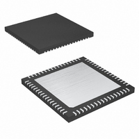
MAXQ2000-RAX+ Maxim Integrated Products, MAXQ2000-RAX+ Datasheet - Page 28

MAXQ2000-RAX+
Manufacturer Part Number
MAXQ2000-RAX+
Description
IC MCU 32K FLASH 68-QFN
Manufacturer
Maxim Integrated Products
Series
MAXQ™r
Datasheet
1.MAXQ2000-RAX.pdf
(39 pages)
Specifications of MAXQ2000-RAX+
Core Processor
RISC
Core Size
16-Bit
Speed
20MHz
Connectivity
1-Wire, SPI, UART/USART
Peripherals
LCD, POR, PWM, WDT
Number Of I /o
50
Program Memory Size
64KB (32K x 16)
Program Memory Type
FLASH
Ram Size
2K x 8
Voltage - Supply (vcc/vdd)
1.8 V ~ 2.75 V
Oscillator Type
Internal
Operating Temperature
-40°C ~ 85°C
Package / Case
68-QFN Exposed Pad
Processor Series
MAXQ
Core
RISC
Data Bus Width
16 bit
Data Ram Size
2 KB
Interface Type
JTAG, SPI
Maximum Clock Frequency
20 MHz
Number Of Programmable I/os
55
Number Of Timers
3
Operating Supply Voltage
2.5 V
Maximum Operating Temperature
+ 85 C
Mounting Style
SMD/SMT
Minimum Operating Temperature
- 40 C
Controller Family/series
MAXQ
No. Of I/o's
50
Ram Memory Size
2048Byte
Cpu Speed
20MHz
No. Of Timers
3
Embedded Interface Type
SPI, UART
Rohs Compliant
Yes
Development Tools By Supplier
MAXQ2000-KIT
Lead Free Status / RoHS Status
Lead free / RoHS Compliant
Eeprom Size
-
Data Converters
-
Lead Free Status / Rohs Status
Lead free / RoHS Compliant
Low-Power LCD Microcontroller
An internal power-on reset circuit enhances system reli-
ability. This circuit forces the device to perform a
power-on reset whenever a rising voltage on V
climbs above approximately 1.8V. At this point the fol-
lowing events occur:
• All registers and circuits enter their reset state
• The POR flag (WDCN.7) is set to indicate the source
• The ring oscillator becomes the clock source and
• Code execution begins at location 8000h
The watchdog timer functions are described in the
MAXQ Family User’s Guide . Execution resumes at loca-
tion 8000h following a watchdog timer reset.
Asserting the external RESET pin low causes the device
to enter the reset state. The external reset functions as
described in the MAXQ Family User’s Guide . Execution
resumes at location 8000h after the RESET pin is
released.
Figure 3. Type-C/D Port Pin Schematic
28
of the reset
____________________________________________________________________
PI.x OR SF INPUT
SF DIRECTION
FLAG
SF OUTPUT
SF ENABLE
PD.x
PO.x
Watchdog Timer Reset
External System Reset
INTERRUPT
FLAG
Power-On Reset
CIRCUIT
DETECT
EIES.x
DDIO
TYPE-D PORT ONLY
The microcontroller uses the type C and type D bidirec-
tional I/O ports described in the MAXQ Family User’s
Guide . The use of two port types allows for maximum
flexibility when interfacing to external peripherals. Each
port has eight independent, general-purpose I/O pins
and three configure/control registers. Many pins support
alternate functions such as timers or interrupts, which are
enabled, controlled, and monitored by dedicated periph-
eral registers. Using the alternate function automatically
converts the pin to that function.
Type-C port pins have Schmitt Trigger receivers and
full CMOS output drivers, and can support alternate
functions. The pin is either tri-stated or weak pullup
when defined as an input, dependent on the state of
the corresponding bit in the output register.
Type-D port pins have Schmitt Trigger receivers and
full CMOS output drivers, and can support alternate
functions. The pin is either tri-stated or weak pullup
when defined as an input, dependent on the state of
the corresponding bit in the output register. All type-D
pins also have interrupt capability.
MAXQ2000
I/O PAD
V
DDIO
V
WEAK
DDIO
PIN.x
I/O Ports


