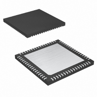
MAXQ2000-RAX+ Maxim Integrated Products, MAXQ2000-RAX+ Datasheet - Page 7

MAXQ2000-RAX+
Manufacturer Part Number
MAXQ2000-RAX+
Description
IC MCU 32K FLASH 68-QFN
Manufacturer
Maxim Integrated Products
Series
MAXQ™r
Datasheet
1.MAXQ2000-RAX.pdf
(39 pages)
Specifications of MAXQ2000-RAX+
Core Processor
RISC
Core Size
16-Bit
Speed
20MHz
Connectivity
1-Wire, SPI, UART/USART
Peripherals
LCD, POR, PWM, WDT
Number Of I /o
50
Program Memory Size
64KB (32K x 16)
Program Memory Type
FLASH
Ram Size
2K x 8
Voltage - Supply (vcc/vdd)
1.8 V ~ 2.75 V
Oscillator Type
Internal
Operating Temperature
-40°C ~ 85°C
Package / Case
68-QFN Exposed Pad
Processor Series
MAXQ
Core
RISC
Data Bus Width
16 bit
Data Ram Size
2 KB
Interface Type
JTAG, SPI
Maximum Clock Frequency
20 MHz
Number Of Programmable I/os
55
Number Of Timers
3
Operating Supply Voltage
2.5 V
Maximum Operating Temperature
+ 85 C
Mounting Style
SMD/SMT
Minimum Operating Temperature
- 40 C
Controller Family/series
MAXQ
No. Of I/o's
50
Ram Memory Size
2048Byte
Cpu Speed
20MHz
No. Of Timers
3
Embedded Interface Type
SPI, UART
Rohs Compliant
Yes
Development Tools By Supplier
MAXQ2000-KIT
Lead Free Status / RoHS Status
Lead free / RoHS Compliant
Eeprom Size
-
Data Converters
-
Lead Free Status / Rohs Status
Lead free / RoHS Compliant
TQFN-EP QFN-EP
23, 35
40
22
45
46
47
48
28
42
41
28, 42
PIN
49
27
54
55
56
57
33
51
50
36, 62
39, 63
LQFP
70
83
84
85
86
50
76
71
HFXOUT
RESET
NAME
HFXIN
V
V
V
V
GND
V
V
DDIO
LCD1
LCD2
LCD
ADJ
DD
_____________________________________________________________________
Low-Power LCD Microcontroller
Digital Supply Voltage
I/O Supply Voltage
Ground
LCD Bias-Control Voltage. Highest LCD drive voltage used with static bias. Connected
to an external source.
LCD Bias, Voltage 1. LCD drive voltage used with 1/2 and 1/3 LCD bias. An internal
resistor- divider sets the voltage. External resistors and capacitors can be used to
change the LCD voltage or drive capability at this pin.
LCD Bias, Voltage 2. LCD drive voltage used with 1/3 LCD bias. An internal
resistor-divider sets the voltage. External resistors and capacitors can be used to
change LCD voltage or drive capability at this pin.
LCD Adjustment Voltage. Connect to an external resistor to provide external control
of the LCD contrast. Leave disconnected for internal contrast adjustment.
Digital, Active-Low, Reset Input/Output. The CPU is held in reset when this is low
and begins executing from the reset vector when released. The pin includes pullup
current source and should be driven by an open-drain, external source capable of
sinking in excess of 2mA. This pin is driven low as an output when an internal reset
condition occurs.
High-Frequency Crystal Input. Connect an external crystal or resonator between
HFXIN and HFXOUT as the high-frequency system clock. Alternatively, HFXIN is the
input for an external, high-frequency clock source when HFXOUT is floating.
High-Frequency Crystal Output/Input. Connect an external crystal or resonator
between HFXIN and HFXOUT as the high-frequency system clock. Alternatively,
float HFXOUT when an external, high-frequency clock source is connected to the
HFXIN pin.
8
7
6
5
4
3
2
1
0
0
T
A
= -40°C
DIGITAL SUPPLY CURRENT
T
vs. CLOCK FREQUENCY
A
= +85°C
5
f
HFIN
T
A
10
(MHz)
T
= 0°C
A
= +25°C
Typical Operating Characteristics
15
V
DD
= 2.75V
20
FUNCTION
Pin Description
7


