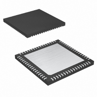
MAXQ2000-RAX+ Maxim Integrated Products, MAXQ2000-RAX+ Datasheet - Page 29

MAXQ2000-RAX+
Manufacturer Part Number
MAXQ2000-RAX+
Description
IC MCU 32K FLASH 68-QFN
Manufacturer
Maxim Integrated Products
Series
MAXQ™r
Datasheet
1.MAXQ2000-RAX.pdf
(39 pages)
Specifications of MAXQ2000-RAX+
Core Processor
RISC
Core Size
16-Bit
Speed
20MHz
Connectivity
1-Wire, SPI, UART/USART
Peripherals
LCD, POR, PWM, WDT
Number Of I /o
50
Program Memory Size
64KB (32K x 16)
Program Memory Type
FLASH
Ram Size
2K x 8
Voltage - Supply (vcc/vdd)
1.8 V ~ 2.75 V
Oscillator Type
Internal
Operating Temperature
-40°C ~ 85°C
Package / Case
68-QFN Exposed Pad
Processor Series
MAXQ
Core
RISC
Data Bus Width
16 bit
Data Ram Size
2 KB
Interface Type
JTAG, SPI
Maximum Clock Frequency
20 MHz
Number Of Programmable I/os
55
Number Of Timers
3
Operating Supply Voltage
2.5 V
Maximum Operating Temperature
+ 85 C
Mounting Style
SMD/SMT
Minimum Operating Temperature
- 40 C
Controller Family/series
MAXQ
No. Of I/o's
50
Ram Memory Size
2048Byte
Cpu Speed
20MHz
No. Of Timers
3
Embedded Interface Type
SPI, UART
Rohs Compliant
Yes
Development Tools By Supplier
MAXQ2000-KIT
Lead Free Status / RoHS Status
Lead free / RoHS Compliant
Eeprom Size
-
Data Converters
-
Lead Free Status / Rohs Status
Lead free / RoHS Compliant
The hardware multiplier module performs high-speed
multiply, square, and accumulate operations, and can
complete a 16-bit x 16-bit multiply-and-accumulate
operation in a single cycle. The hardware multiplier
consists of two 16-bit parallel-load operand registers
(MA, MB), an accumulator that is formed by up to three
16-bit parallel registers (MC2, MC1, and MC0), and a
status/control register (MCNT). Loading the registers
can automatically initiate the operation, saving time on
repetitive calculations. The accumulate function of the
hardware multiplier is an essential element of digital fil-
tering, signal processing, and PID control systems.
The hardware multiplier module supports the following
operations:
• Multiply unsigned (16 bit x 16 bit)
• Multiply signed (16 bit x 16 bit)
• Multiply-Accumulate unsigned (16 bit x 16 bit)
• Multiply-Accumulate signed (16 bit x 16 bit)
• Square unsigned (16 bit)
• Square signed (16 bit)
• Square-Accumulate unsigned (16 bit)
• Square-Accumulate signed (16 bit)
A binary real-time clock keeps the time of day in
absolute seconds with 1/256-second resolution. The
32-bit second counter can count up to approximately
136 years and be translated to calendar format by the
application software. A time-of-day alarm and indepen-
dent subsecond alarm can cause an interrupt, or wake
the device from Stop mode.
The independent subsecond alarm runs from the same
RTC, and allows the application to perform periodic
interrupts up to ones with a granularity of approximately
3.9ms. This creates an additional timer that can be
used to measure long periods without performance
degradations. Traditionally, long time periods have
been measured using multiple interrupts from shorter
programmable timers. Each timer interrupt required
servicing, with each accompanying interruption slowing
system operation. By using the RTC subsecond timer
as a long-period timer, only one interrupt is needed,
eliminating the performance hit associated with using a
shorter timer.
High-Speed Hardware Multiplier
Real-Time Clock
____________________________________________________________________
Low-Power LCD Microcontroller
An internal crystal oscillator clocks the RTC using inte-
grated 6pF load capacitors, and give the best perfor-
mance when mated with a 32.768kHz crystal rated for a
6pF load. No external load capacitors are required.
Higher accuracy can be obtained by supplying an exter-
nal clock source to the RTC. The frequency accuracy of
a crystal-based oscillator circuit is dependent upon crys-
tal accuracy, the match between the crystal and the
oscillator capacitor load, ambient temperature, etc. An
error of 20ppm is equivalent to approximately 1 minute
per month.
The microcontroller incorporates three 16-bit program-
mable instances of the Timer 2 peripheral, denoted
TR2A, TR2B, and TR2C. These timers can be used in
counter/timer/capture/compare/PWM functions, allow-
ing precise control of internal and external events.
Timer 2 supports optional single-shot, external gating,
and polarity control options.
The Timer 2 peripheral includes the following:
• 16-bit autoreload timer/counter
• 16-bit capture
• 16-bit counter
• 8-bit capture and 8-bit timer
• 8-bit counter and 8-bit timer
An internal watchdog timer greatly increases system
reliability. The timer resets the device if software execu-
tion is disturbed. The watchdog timer is a free-running
counter designed to be periodically reset by the appli-
cation software. If software is operating correctly, the
counter will be periodically reset and never reach its
maximum count. However, if software operation is inter-
rupted, the timer does not reset, triggering a system
reset and optionally a watchdog timer interrupt. This
protects the system against electrical noise or electro-
static discharge (ESD) upsets that could cause uncon-
trolled processor operation. The internal watchdog
timer is an upgrade to older designs with external
watchdog devices, reducing system cost and simulta-
neously increasing reliability.
Programmable Timers
Watchdog Timer
Timer 2
29


