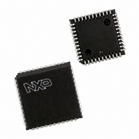
P87C51MC2BA/02,529 NXP Semiconductors, P87C51MC2BA/02,529 Datasheet - Page 33

P87C51MC2BA/02,529
Manufacturer Part Number
P87C51MC2BA/02,529
Description
IC 80C51 MCU 96K OTP 44-PLCC
Manufacturer
NXP Semiconductors
Series
87Cr
Datasheet
1.P87C51MB2BA02529.pdf
(36 pages)
Specifications of P87C51MC2BA/02,529
Program Memory Type
OTP
Program Memory Size
96KB (96K x 8)
Package / Case
44-PLCC
Core Processor
8051
Core Size
8-Bit
Speed
24MHz
Connectivity
EBI/EMI, SPI, UART/USART
Peripherals
POR, PWM, WDT
Number Of I /o
34
Ram Size
3K x 8
Voltage - Supply (vcc/vdd)
2.7 V ~ 5.5 V
Oscillator Type
Internal
Operating Temperature
0°C ~ 70°C
Processor Series
P87C5x
Core
80C51
Data Bus Width
8 bit
Data Ram Size
3 KB
Interface Type
SPI, UART
Maximum Clock Frequency
24 MHz
Number Of Programmable I/os
34
Number Of Timers
3
Operating Supply Voltage
2.7 V to 5.5 V
Maximum Operating Temperature
+ 70 C
Mounting Style
SMD/SMT
3rd Party Development Tools
PK51, CA51, A51, ULINK2
Minimum Operating Temperature
0 C
Cpu Family
87C
Device Core
80C51
Device Core Size
8b
Frequency (max)
24MHz
Total Internal Ram Size
3KB
# I/os (max)
34
Number Of Timers - General Purpose
3
Operating Supply Voltage (typ)
3.3/5V
Operating Supply Voltage (max)
5.5V
Operating Supply Voltage (min)
2.7V
Instruction Set Architecture
CISC
Operating Temp Range
0C to 70C
Operating Temperature Classification
Commercial
Mounting
Surface Mount
Pin Count
44
Package Type
PLCC
Lead Free Status / RoHS Status
Lead free / RoHS Compliant
For Use With
OM10064 - EMULATOR 80C51 PDS51-MK2
Eeprom Size
-
Data Converters
-
Lead Free Status / Rohs Status
Compliant
Other names
568-1244-5
935273219529
P87C51MC2BA/02-S
935273219529
P87C51MC2BA/02-S
Available stocks
Company
Part Number
Manufacturer
Quantity
Price
Company:
Part Number:
P87C51MC2BA/02,529
Manufacturer:
NXP Semiconductors
Quantity:
10 000
Philips Semiconductors
9397 750 12302
Product data
[3]
[4]
[5]
[6]
[7]
[8]
[9]
These transparent plastic packages are extremely sensitive to reflow soldering conditions and must
on no account be processed through more than one soldering cycle or subjected to infrared reflow
soldering with peak temperature exceeding 217 C
oven. The package body peak temperature must be kept as low as possible.
These packages are not suitable for wave soldering. On versions with the heatsink on the bottom
side, the solder cannot penetrate between the printed-circuit board and the heatsink. On versions with
the heatsink on the top side, the solder might be deposited on the heatsink surface.
If wave soldering is considered, then the package must be placed at a 45 angle to the solder wave
direction. The package footprint must incorporate solder thieves downstream and at the side corners.
Wave soldering is suitable for LQFP, QFP and TQFP packages with a pitch (e) larger than 0.8 mm; it
is definitely not suitable for packages with a pitch (e) equal to or smaller than 0.65 mm.
Wave soldering is suitable for SSOP and TSSOP packages with a pitch (e) equal to or larger than
0.65 mm; it is definitely not suitable for packages with a pitch (e) equal to or smaller than 0.5 mm.
Image sensor packages in principle should not be soldered. They are mounted in sockets or delivered
pre-mounted on flex foil. However, the image sensor package can be mounted by the client on a flex
foil by using a hot bar soldering process. The appropriate soldering profile can be provided on
request.
Hot bar soldering or manual soldering is suitable for PMFP packages.
Rev. 03 — 13 November 2003
P87C51MB2/P87C51MC2
10 C measured in the atmosphere of the reflow
80C51 8-bit microcontroller family
© Koninklijke Philips Electronics N.V. 2003. All rights reserved.
33 of 36


