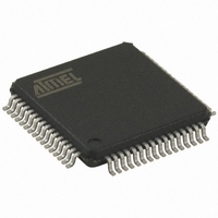
AT90CAN64-16AUR Atmel, AT90CAN64-16AUR Datasheet - Page 236

AT90CAN64-16AUR
Manufacturer Part Number
AT90CAN64-16AUR
Description
MCU AVR 64K FLASH 16MHZ 64TQFP
Manufacturer
Atmel
Series
AVR® 90CANr
Datasheet
1.AT90CAN32-16AUR.pdf
(428 pages)
Specifications of AT90CAN64-16AUR
Core Processor
AVR
Core Size
8-Bit
Speed
16MHz
Connectivity
CAN, EBI/EMI, I²C, SPI, UART/USART
Peripherals
Brown-out Detect/Reset, POR, PWM, WDT
Number Of I /o
53
Program Memory Size
64KB (64K x 8)
Program Memory Type
FLASH
Eeprom Size
2K x 8
Ram Size
4K x 8
Voltage - Supply (vcc/vdd)
2.7 V ~ 5.5 V
Data Converters
A/D 8x10b
Oscillator Type
Internal
Operating Temperature
-40°C ~ 85°C
Package / Case
64-TQFP, 64-VQFP
Data Bus Width
8 bit
Data Ram Size
4 KB
Mounting Style
SMD/SMT
Lead Free Status / RoHS Status
Lead free / RoHS Compliant
Available stocks
Company
Part Number
Manufacturer
Quantity
Price
- Current page: 236 of 428
- Download datasheet (6Mb)
19.2.2.2
Figure 19-2. CAN Extended Frames
19.2.2.3
19.2.3
19.2.3.1
236
Interframe
Interframe
Bus Idle
Bus Idle
Data Frame
Remote Frame
Space
Space
AT90CAN32/64/128
CAN Bit Timing
SOF
SOF
SOF
SOF
CAN Extended Frame
Format Co-existence
Bit Construction
11-bit base identifier
11-bit base identifier
IDT28..18
IDT28..18
A message in the CAN extended frame format is likely the same as a message in CAN standard
frame format. The difference is the length of the identifier used. The identifier is made up of the
existing 11-bit identifier (base identifier) and an 18-bit extension (identifier extension). The dis-
tinction between CAN standard frame format and CAN extended frame format is made by using
the IDE bit which is transmitted as dominant in case of a frame in CAN standard frame format,
and transmitted as recessive in the other case.
As the two formats have to co-exist on one bus, it is laid down which message has higher priority
on the bus in the case of bus access collision with different formats and the same identifier /
base identifier: The message in CAN standard frame format always has priority over the mes-
sage in extended format.
There are three different types of CAN modules available:
To ensure correct sampling up to the last bit, a CAN node needs to re-synchronize throughout
the entire frame. This is done at the beginning of each message with the falling edge SOF and
on each recessive to dominant edge.
One CAN bit time is specified as four non-overlapping time segments. Each segment is con-
structed from an integer multiple of the Time Quantum. The Time Quantum or TQ is the smallest
discrete timing resolution used by a CAN node.
SRR IDE
SRR IDE
Arbitration
Arbitration
– 2.0A - Considers 29 bit ID as an error
– 2.0B Passive - Ignores 29 bit ID messages
– 2.0B Active - Handles both 11 and 29 bit ID Messages
Field
Field
18-bit identifier extension
18-bit identifier extension
ID17..0
ID17..0
RTR
RTR
r1
r1
r0
r0
Control
Control
Field
Field
4-bit DLC
4-bit DLC
DLC4..0
DLC4..0
15-bit CRC
CRC
Field
0 - 8 bytes
Data
Field
CRC
del.
ACK
Field
ACK
ACK
del.
15-bit CRC
End of
Frame
7 bits
CRC
Field
CRC
Intermission
del.
3 bits
ACK
Field
ACK
Interframe
ACK
Space
del.
(Indefinite)
Bus Idle
End of
Frame
7 bits
7679H–CAN–08/08
Intermission
3 bits
Interframe
Space
(Indefinite)
Bus Idle
Related parts for AT90CAN64-16AUR
Image
Part Number
Description
Manufacturer
Datasheet
Request
R

Part Number:
Description:
Manufacturer:
Atmel Corporation
Datasheet:

Part Number:
Description:
Manufacturer:
Atmel Corporation
Datasheet:

Part Number:
Description:
IC MCU AVR 64K FLASH 64-TQFP
Manufacturer:
Atmel
Datasheet:

Part Number:
Description:
IC MCU AVR 64K FLASH 64-QFN
Manufacturer:
Atmel
Datasheet:

Part Number:
Description:
At90can128 8-bit Avr Microcontroller With 32k Bytes Of Isp Flash And Can Controller
Manufacturer:
ATMEL Corporation
Datasheet:

Part Number:
Description:
8-bit Microcontrollers - MCU 64 KB FLASH - 16MHz
Manufacturer:
Atmel

Part Number:
Description:
8-bit Microcontrollers - MCU Microcontroller
Manufacturer:
Atmel

Part Number:
Description:
DEV KIT FOR AVR/AVR32
Manufacturer:
Atmel
Datasheet:


