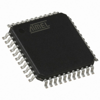
AT89C51RE2-RLTUM Atmel, AT89C51RE2-RLTUM Datasheet - Page 54

AT89C51RE2-RLTUM
Manufacturer Part Number
AT89C51RE2-RLTUM
Description
MCU 8051 128K FLASH 44-VQFP
Manufacturer
Atmel
Series
89Cr
Datasheet
1.AT89C51RE2-SLSUM.pdf
(187 pages)
Specifications of AT89C51RE2-RLTUM
Core Processor
8051
Core Size
8-Bit
Speed
60MHz
Connectivity
I²C, SPI, UART/USART
Peripherals
POR, PWM, WDT
Number Of I /o
34
Program Memory Size
128KB (128K x 8)
Program Memory Type
FLASH
Ram Size
8K x 8
Voltage - Supply (vcc/vdd)
2.7 V ~ 5.5 V
Oscillator Type
External
Operating Temperature
-40°C ~ 85°C
Package / Case
44-TQFP, 44-VQFP
Processor Series
AT89x
Core
8051
Data Bus Width
8 bit
Data Ram Size
8 KB
Interface Type
UART, SPI
Maximum Clock Frequency
60 MHz
Number Of Programmable I/os
34
Number Of Timers
3
Operating Supply Voltage
2.7 V to 5.5 V
Maximum Operating Temperature
+ 85 C
Mounting Style
SMD/SMT
3rd Party Development Tools
PK51, CA51, A51, ULINK2
Development Tools By Supplier
AT89OCD-01
Minimum Operating Temperature
- 40 C
Height
1.45 mm
Length
10.1 mm
Supply Voltage (max)
5.5 V
Supply Voltage (min)
2.7 V
Width
10.1 mm
For Use With
AT89STK-11 - KIT STARTER FOR AT89C51RX2
Lead Free Status / RoHS Status
Lead free / RoHS Compliant
Eeprom Size
-
Data Converters
-
Lead Free Status / Rohs Status
Details
Available stocks
Company
Part Number
Manufacturer
Quantity
Price
Company:
Part Number:
AT89C51RE2-RLTUM
Manufacturer:
MSC
Quantity:
1 560
Bootloader
Description
Entry points
Boot Process
Description
Hardware boot process
request detection
Communication link
detection
54
AT89C51RE2
PSEN=0
Yes
After reset only one bootloader entry point is possible. This entry point stands at address 0x0000
of the boot ROM memory. This entry point executes the boot process of the bootloader.
The bootloader entry point can be selected through two processes:
At reset, if the hardware conditions are applied, the bootloader entry point is accessed and
executed.
At reset, if the hardware conditions are not set and the BRV2-0 is programmed ‘011’, the boot-
loader entry point is accessed and the bootprocess is started.
The boot process consists in three main operations:
•
•
•
The hardware boot process request is detected when the hardware conditions (under reset,
EA=1 and PSEN=0) are received by the processor or when no hardware condition is applied
and the BRV2:0 is configured ‘011’.
Two interfaces are available for ISP:
•
•
RESET
EA=1
The hardware boot process request detection
The communication link detection (Uart or OCD)
The start-up of the bootloader
UART0
OCD UART
Communication link
detector / initialiser
PC = RM0 @0x0000h
Start Bootloader
No
BRV=’011’
Yes
No
BRV=’100’
Yes
No
BRV=’101’
Yes
Start Application
No
BRV=’110’
Yes
7663E–8051–10/08
No


