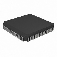
PIC17LC756A-08I/L Microchip Technology, PIC17LC756A-08I/L Datasheet - Page 110

PIC17LC756A-08I/L
Manufacturer Part Number
PIC17LC756A-08I/L
Description
IC MCU OTP 16KX16 A/D 68PLCC
Manufacturer
Microchip Technology
Series
PIC® 17Cr
Specifications of PIC17LC756A-08I/L
Core Processor
PIC
Core Size
8-Bit
Speed
8MHz
Connectivity
I²C, SPI, UART/USART
Peripherals
Brown-out Detect/Reset, POR, PWM, WDT
Number Of I /o
50
Program Memory Size
32KB (16K x 16)
Program Memory Type
OTP
Ram Size
902 x 8
Voltage - Supply (vcc/vdd)
3 V ~ 5.5 V
Data Converters
A/D 12x10b
Oscillator Type
External
Operating Temperature
-40°C ~ 85°C
Package / Case
68-PLCC
Processor Series
PIC17LC
Core
PIC
Data Bus Width
8 bit
Data Ram Size
902 B
Interface Type
I2C, MSSP, RS- 232, SCI, SPI, USART
Maximum Clock Frequency
8 MHz
Number Of Programmable I/os
50
Number Of Timers
8
Operating Supply Voltage
3 V to 5.5 V
Maximum Operating Temperature
+ 85 C
Mounting Style
SMD/SMT
Minimum Operating Temperature
- 40 C
On-chip Adc
12 bit
Lead Free Status / RoHS Status
Lead free / RoHS Compliant
Eeprom Size
-
Lead Free Status / Rohs Status
Details
Available stocks
Company
Part Number
Manufacturer
Quantity
Price
Company:
Part Number:
PIC17LC756A-08I/L
Manufacturer:
MICROCHIP
Quantity:
3 000
Company:
Part Number:
PIC17LC756A-08I/L
Manufacturer:
Microchip Technology
Quantity:
10 000
- Current page: 110 of 304
- Download datasheet (6Mb)
PIC17C7XX
13.2
Timer3 is a 16-bit timer consisting of the TMR3H and
TMR3L registers. TMR3H is the high byte of the timer
and TMR3L is the low byte. This timer has an associ-
ated 16-bit period register (PR3H/CA1H:PR3L/CA1L).
This period register can be software configured to be a
another 16-bit capture register.
When the TMR3CS bit (TCON1<2>) is clear, the timer
increments every instruction cycle (F
TMR3CS is set, the counter increments on every falling
edge of the RB5/TCLK3 pin. In either mode, the
TMR3ON bit must be set for the timer/counter to incre-
ment. When TMR3ON is clear, the timer will not incre-
ment or set flag bit TMR3IF.
Timer3 has two modes of operation, depending on the
CA1/PR3 bit (TCON2<3>). These modes are:
• Three capture and one period register mode
• Four capture register mode
The PIC17C7XX has up to four 16-bit capture registers
that capture the 16-bit value of TMR3 when events are
detected on capture pins. There are four capture pins
FIGURE 13-5:
DS30289B-page 110
RB5/TCLK3
RB1/CAP2
RG4/CAP3
RE3/CAP4
Timer3
CA2ED1: CA2ED0
(TCON1<7:6>)
CA3ED1: CA3ED0
(TCON3<2:1>)
CA4ED1: CA4ED0
(TCON3<4:3>)
Prescaler select
Prescaler select
Prescaler select
F
OSC
Edge select,
Edge select,
Edge select,
TIMER3 WITH THREE CAPTURE AND ONE PERIOD REGISTER BLOCK DIAGRAM
/4
2
2
2
TMR3CS
(TCON1<2>)
1
0
TMR3ON
(TCON2<2>)
Set CA2IF
(PIR1<3>)
Set CA3IF
(PIR2<2>)
Set CA4IF
(PIR2<3>)
OSC
Capture2
Enable
CA2H
Capture3
CA3H
Capture4
CA4H
Enable
Enable
/4). When
PR3H/CA1H
CA2L
TMR3H
CA3L
CA4L
Comparator<8>
Comparator x16
(RB0/CAP1, RB1/CAP2, RG4/CAP3, and RE3/CAP4),
one for each capture register pair. The capture pins are
multiplexed with the I/O pins. An event can be:
• A rising edge
• A falling edge
• Every 4th rising edge
• Every 16th rising edge
Each 16-bit capture register has an interrupt flag asso-
ciated with it. The flag is set when a capture is made.
The capture modules are truly part of the Timer3 block.
Figure 13-5 and Figure 13-6 show the block diagrams
for the two modes of operation.
13.2.1
In this mode, registers PR3H/CA1H and PR3L/CA1L
constitute a 16-bit period register. A block diagram is
shown in Figure 13-5. The timer increments until it
equals the period register and then resets to 0000h on
the next timer clock. TMR3 Interrupt Flag bit (TMR3IF)
is set at this point. This interrupt can be disabled by
clearing the TMR3 Interrupt Enable bit (TMR3IE).
TMR3IF must be cleared in software.
PR3L/CA1L
TMR3L
THREE CAPTURE AND ONE
PERIOD REGISTER MODE
Reset
Equal
2000 Microchip Technology Inc.
Set TMR3IF
(PIR1<6>)
Related parts for PIC17LC756A-08I/L
Image
Part Number
Description
Manufacturer
Datasheet
Request
R

Part Number:
Description:
MICRO CTRL 16K LOW PWR 68PLCC
Manufacturer:
Microchip Technology
Datasheet:

Part Number:
Description:
MICRO CTRL 16K LOW PWR 64SDIP
Manufacturer:
Microchip Technology
Datasheet:

Part Number:
Description:
MICRO CTRL 16K LOW PWR 64SDIP
Manufacturer:
Microchip Technology
Datasheet:

Part Number:
Description:
MICRO CTRL 16K LOW PWR 68PLCC
Manufacturer:
Microchip Technology
Datasheet:

Part Number:
Description:
Manufacturer:
Microchip Technology Inc.
Datasheet:

Part Number:
Description:
Manufacturer:
Microchip Technology Inc.
Datasheet:

Part Number:
Description:
Manufacturer:
Microchip Technology Inc.
Datasheet:

Part Number:
Description:
Manufacturer:
Microchip Technology Inc.
Datasheet:

Part Number:
Description:
Manufacturer:
Microchip Technology Inc.
Datasheet:

Part Number:
Description:
Manufacturer:
Microchip Technology Inc.
Datasheet:

Part Number:
Description:
Manufacturer:
Microchip Technology Inc.
Datasheet:


