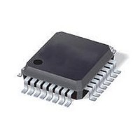
ST7FMC1K4T6 STMicroelectronics, ST7FMC1K4T6 Datasheet - Page 82

ST7FMC1K4T6
Manufacturer Part Number
ST7FMC1K4T6
Description
MCU 8BIT 16K FLASH 32TQFP
Manufacturer
STMicroelectronics
Series
ST7r
Datasheet
1.ST7FMC2S4T6.pdf
(309 pages)
Specifications of ST7FMC1K4T6
Core Processor
ST7
Core Size
8-Bit
Speed
8MHz
Connectivity
LINSCI
Peripherals
LVD, Motor Control PWM, POR, PWM, WDT
Number Of I /o
17
Program Memory Size
16KB (16K x 8)
Program Memory Type
FLASH
Ram Size
768 x 8
Voltage - Supply (vcc/vdd)
3.8 V ~ 5.5 V
Data Converters
A/D 16x10b
Oscillator Type
Internal
Operating Temperature
-40°C ~ 85°C
Package / Case
32-LQFP
Processor Series
ST7FMC1x
Core
ST7
Data Bus Width
8 bit
Data Ram Size
768 B
Interface Type
SCI, SPI
Maximum Clock Frequency
8 MHz
Number Of Programmable I/os
60
Number Of Timers
3
Operating Supply Voltage
4.5 V to 5.5 V
Maximum Operating Temperature
+ 85 C
Mounting Style
SMD/SMT
Development Tools By Supplier
ST7MC-KIT/BLDC, ST7MDT50-EMU3, STX-RLINK
Minimum Operating Temperature
- 40 C
On-chip Adc
10 bit, 16 Channel
For Use With
497-8402 - BOARD EVAL COMPLETE INVERTER497-8400 - KIT IGBT PWR MODULE CTRL ST7MC497-4734 - EVAL KIT 3KW POWER DRIVER BOARD497-4733 - EVAL KIT 1KW POWER DRIVER BOARD497-4732 - EVAL KIT 300W POWER DRIVER BOARD497-4731 - EVAL KIT PWR DRIVER CONTROL BRD
Lead Free Status / RoHS Status
Lead free / RoHS Compliant
Eeprom Size
-
Lead Free Status / Rohs Status
Details
Other names
497-4866
Available stocks
Company
Part Number
Manufacturer
Quantity
Price
Company:
Part Number:
ST7FMC1K4T6
Manufacturer:
ST
Quantity:
292
Company:
Part Number:
ST7FMC1K4T6
Manufacturer:
STMicroelectronics
Quantity:
10 000
- Current page: 82 of 309
- Download datasheet (6Mb)
ST7MC1xx/ST7MC2xx
16-BIT TIMER (Cont’d)
10.3.3.4 Output Compare
In this section, the index, i, may be 1 or 2 because
there are 2 output compare functions in the 16-bit
timer.
This function can be used to control an output
waveform or indicate when a period of time has
elapsed.
When a match is found between the Output Com-
pare register and the free running counter, the out-
put compare function:
Two 16-bit registers Output Compare Register 1
(OC1R) and Output Compare Register 2 (OC2R)
contain the value to be compared to the counter
register each timer clock cycle.
These registers are readable and writable and are
not affected by the timer hardware. A reset event
changes the OC
Timing resolution is one count of the free running
counter: (
Procedure:
To use the output compare function, select the fol-
lowing in the CR2 register:
– Set the OCiE bit if an output is needed then the
– Select the timer clock (CC[1:0]) (see
And select the following in the CR1 register:
– Select the OLVLi bit to applied to the OCMPi pins
– Set the OCIE bit to generate an interrupt if it is
When a match is found between OCRi register
and CR register:
– OCFi bit is set.
82/309
1
OCMPi pin is dedicated to the output compare i
signal.
Clock Control
after the match occurs.
needed.
– Assigns pins with a programmable value if the
– Sets a flag in the status register
– Generates an interrupt if enabled
OCiR
OCIE bit is set
f
CPU/
CC[1:0]
Bits).
i
R value to 8000h.
MS Byte
OCiHR
).
LS Byte
OCiLR
Table 16
– The OCMPi pin takes OLVLi bit value (OCMPi
– A timer interrupt is generated if the OCIE bit is
The OC
ing application can be calculated using the follow-
ing formula:
Where:
Δ
f
PRESC
If the timer clock is an external clock, the formula
is:
Where:
Δ
f
Clearing the output compare interrupt request (i.e.
clearing the OCFi bit) is done by:
1. Reading the SR register while the OCFi bit is
2. An access (read or write) to the OCiLR register.
The following procedure is recommended to pre-
vent the OCFi bit from being set between the time
it is read and the write to the OC
– Write to the OCiHR register (further compares
– Read the SR register (first step of the clearance
– Write to the OCiLR register (enables the output
CPU
EXT
t
t
pin latch is forced low during reset).
set in the CR2 register and the I bit is cleared in
the CC register (CC).
are inhibited).
of the OCFi bit, which may be already set).
compare function and clears the OCFi bit).
set.
i
R register value required for a specific tim-
= Output compare period (in seconds)
= CPU clock frequency (in hertz)
= Timer prescaler factor (2, 4 or 8 de-
= Output compare period (in seconds)
= External timer clock frequency (in hertz)
pending on CC[1:0] bits, see
Clock Control
Δ
Δ
OCiR =
OCiR =
Δt
Bits)
Δt
*
PRESC
f
EXT
*
f
CPU
i
R register:
Table 16
Related parts for ST7FMC1K4T6
Image
Part Number
Description
Manufacturer
Datasheet
Request
R

Part Number:
Description:
STMicroelectronics [RIPPLE-CARRY BINARY COUNTER/DIVIDERS]
Manufacturer:
STMicroelectronics
Datasheet:

Part Number:
Description:
STMicroelectronics [LIQUID-CRYSTAL DISPLAY DRIVERS]
Manufacturer:
STMicroelectronics
Datasheet:

Part Number:
Description:
BOARD EVAL FOR MEMS SENSORS
Manufacturer:
STMicroelectronics
Datasheet:

Part Number:
Description:
NPN TRANSISTOR POWER MODULE
Manufacturer:
STMicroelectronics
Datasheet:

Part Number:
Description:
TURBOSWITCH ULTRA-FAST HIGH VOLTAGE DIODE
Manufacturer:
STMicroelectronics
Datasheet:

Part Number:
Description:
Manufacturer:
STMicroelectronics
Datasheet:

Part Number:
Description:
DIODE / SCR MODULE
Manufacturer:
STMicroelectronics
Datasheet:

Part Number:
Description:
DIODE / SCR MODULE
Manufacturer:
STMicroelectronics
Datasheet:

Part Number:
Description:
Search -----> STE16N100
Manufacturer:
STMicroelectronics
Datasheet:

Part Number:
Description:
Search ---> STE53NA50
Manufacturer:
STMicroelectronics
Datasheet:

Part Number:
Description:
NPN Transistor Power Module
Manufacturer:
STMicroelectronics
Datasheet:

Part Number:
Description:
DIODE / SCR MODULE
Manufacturer:
STMicroelectronics
Datasheet:


