ST72F264G2B6 STMicroelectronics, ST72F264G2B6 Datasheet - Page 163
ST72F264G2B6
Manufacturer Part Number
ST72F264G2B6
Description
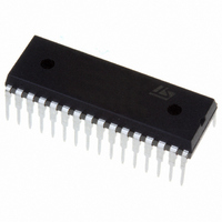
MCU 8-BIT 8K FLASH 32-SDIP
Manufacturer
STMicroelectronics
Series
ST7r
Specifications of ST72F264G2B6
Mfg Application Notes
ST7 Checksum Capability, AN1070 App Note
Core Processor
ST7
Core Size
8-Bit
Speed
16MHz
Connectivity
I²C, SCI, SPI
Peripherals
LVD, POR, PWM, WDT
Number Of I /o
22
Program Memory Size
8KB (8K x 8)
Program Memory Type
FLASH
Ram Size
256 x 8
Voltage - Supply (vcc/vdd)
2.7 V ~ 5.5 V
Data Converters
A/D 6x10b
Oscillator Type
Internal
Operating Temperature
-40°C ~ 85°C
Package / Case
32-SDIP (0.400", 10.16mm)
Processor Series
ST72F2x
Core
ST7
Data Bus Width
8 bit
Data Ram Size
256 B
Interface Type
I2C, SCI, SPI
Maximum Clock Frequency
8 MHz
Number Of Programmable I/os
22
Number Of Timers
3
Maximum Operating Temperature
+ 85 C
Mounting Style
Through Hole
Development Tools By Supplier
ST7F264-IND/USB, ST72F34X-SK/RAIS, ST7MDT10-DVP3, ST7MDT10-EMU3, STX-RLINK
Minimum Operating Temperature
- 40 C
On-chip Adc
10 bit, 6 Channel
For Use With
497-6423 - BOARD EVAL BASED ON ST72264G1497-5046 - KIT TOOL FOR ST7/UPSD/STR7 MCU
Lead Free Status / RoHS Status
Lead free / RoHS Compliant
Eeprom Size
-
Lead Free Status / Rohs Status
Details
Other names
497-5570
Available stocks
Company
Part Number
Manufacturer
Quantity
Price
Company:

Part Number:
ST72F264G2B6
Manufacturer:
ST
Quantity:
10
Company:
Part Number:
ST72F264G2B6
Manufacturer:
NEC
Quantity:
6 097
Part Number:
ST72F264G2B6
Manufacturer:
ST
Quantity:
20 000


DEVICE CONFIGURATION (Cont’d)
OPT 0 = FMP_W FLASH write protection
This option indicates if the FLASH program mem-
ory is write protected.
Warning: When this option is selected, the pro-
gram memory (and the option bit itself) can never
be erased or programmed again.
0: Write protection off
1: Write protection on
USER OPTION BYTE 1
OPT 7 = EXTIT Port C External Interrupt Configu-
ration.
This option bit allows the Port C external interrupt
mapping to be configured as ei0 or ei1.
Table 27. External Interrupt Configuration
OPT 6 = Reserved, must be kept at default value.
OPT 5:4 = OSCTYPE[1:0] Oscillator Type selec-
tion
These option bits select the Oscillator Type.
Resonator Oscillator
Reserved
Internal RC Oscillator
External Source
PC[5:0] Ports
PA[7:0] Ports
PA[7:0] Ports
Clock Source
ei0
PC[5:0] Ports
PB[7:0] Ports
PB[7:0] Ports
OSCTYPE1 OSCTYPE0
ei1
0
1
0
1
option
EXTIT
0
1
0
1
bit
1
0
OPT 3:1 = OSCRNGE[2:0] Oscillator Range se-
lection
These option bits select the oscillator range.
OPT 0 = PLL PLL selection
This option bit selects the PLL which allows multi-
plication by two of the oscillator frequency. The
PLL must not be used with the internal RC oscilla-
tor. It is guaranteed only with a f
cy between 2 and 4MHz.
0: PLL x2 enabled
1: PLL x2 disabled
CAUTION: the PLL can be enabled only if the
“OSC RANGE” (OPT3:1) bits are configured to
“MP - 2~4MHz”. Otherwise, the device functionali-
ty is not guaranteed.
Typ. Freq. Range
VLP 32~100kHz
LP
MP
MS
HS
ST72260Gx, ST72262Gx, ST72264Gx
8~16MHz
1~2MHz
2~4MHz
4~8MHz
RNGE2
OSC
1
0
0
0
0
RNGE1
OSC
OSC
x
0
0
1
1
input frequen-
RNGE0
OSC
163/172
0
1
0
1
x
1
Related parts for ST72F264G2B6
Image
Part Number
Description
Manufacturer
Datasheet
Request
R

Part Number:
Description:
STMicroelectronics [RIPPLE-CARRY BINARY COUNTER/DIVIDERS]
Manufacturer:
STMicroelectronics
Datasheet:
Part Number:
Description:
STMicroelectronics [LIQUID-CRYSTAL DISPLAY DRIVERS]
Manufacturer:
STMicroelectronics
Datasheet:

Part Number:
Description:
BOARD EVAL FOR MEMS SENSORS
Manufacturer:
STMicroelectronics
Datasheet:
Part Number:
Description:
NPN TRANSISTOR POWER MODULE
Manufacturer:
STMicroelectronics
Datasheet:
Part Number:
Description:
TURBOSWITCH ULTRA-FAST HIGH VOLTAGE DIODE
Manufacturer:
STMicroelectronics
Datasheet:
Part Number:
Description:
Manufacturer:
STMicroelectronics
Datasheet:
Part Number:
Description:
DIODE / SCR MODULE
Manufacturer:
STMicroelectronics
Datasheet:
Part Number:
Description:
DIODE / SCR MODULE
Manufacturer:
STMicroelectronics
Datasheet:
Part Number:
Description:
Search -----> STE16N100
Manufacturer:
STMicroelectronics
Datasheet:
Part Number:
Description:
Search ---> STE53NA50
Manufacturer:
STMicroelectronics
Datasheet:
Part Number:
Description:
NPN Transistor Power Module
Manufacturer:
STMicroelectronics
Datasheet:
Part Number:
Description:
DIODE / SCR MODULE
Manufacturer:
STMicroelectronics
Datasheet: