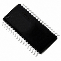
ST72F621L4M1 STMicroelectronics, ST72F621L4M1 Datasheet - Page 117

ST72F621L4M1
Manufacturer Part Number
ST72F621L4M1
Description
IC MCU 8BIT LS 16K 34-SOIC
Manufacturer
STMicroelectronics
Series
ST7r
Datasheet
1.ST72F622L2M1.pdf
(139 pages)
Specifications of ST72F621L4M1
Core Processor
ST7
Core Size
8-Bit
Speed
8MHz
Connectivity
SCI, SPI, USB
Peripherals
DMA, LVD, POR, PWM, WDT
Number Of I /o
23
Program Memory Size
16KB (16K x 8)
Program Memory Type
FLASH
Ram Size
768 x 8
Voltage - Supply (vcc/vdd)
4 V ~ 5.5 V
Data Converters
A/D 8x10b
Oscillator Type
Internal
Operating Temperature
0°C ~ 70°C
Package / Case
34-SOIC (7.5mm Width)
Processor Series
ST72F6x
Core
ST7
Data Bus Width
8 bit
Data Ram Size
768 B
Interface Type
SCI, SPI, USB
Maximum Clock Frequency
12 MHz
Number Of Programmable I/os
23
Number Of Timers
2
Operating Supply Voltage
4 V to 5.5 V
Maximum Operating Temperature
+ 70 C
Mounting Style
SMD/SMT
Minimum Operating Temperature
0 C
On-chip Adc
10 bit
For Use With
497-5046 - KIT TOOL FOR ST7/UPSD/STR7 MCU
Lead Free Status / RoHS Status
Lead free / RoHS Compliant
Eeprom Size
-
Lead Free Status / Rohs Status
In Transition
Other names
497-2112-5
Available stocks
Company
Part Number
Manufacturer
Quantity
Price
Company:
Part Number:
ST72F621L4M1
Manufacturer:
ST
Quantity:
2 272
Company:
Part Number:
ST72F621L4M1
Manufacturer:
ST
Quantity:
5
12.11 COMMUNICATION INTERFACE CHARACTERISTICS
12.11.1 USB - Universal Bus Interface
(Operating conditions T
Notes
1. RL is the load connected on the USB drivers.
2. All the voltages are measured from the local ground potential.
3. Not tested in production, guaranteed by design.
4. To improve EMC performance (noise immunity), it is recommended to connect a 100nF capacitor to the
USBVCC pin.
Figure 77. USB: Data Signal Rise and Fall Time
Table 26.
Note 1: Measured from 10% to 90% of the data signal. For more detailed informations, please refer to Chapter 7 (Elec-
trical) of the USB specification (version 1.1).
USB DC Electrical Characteristics
Differential Common Mode Range
Single Ended Receiver Threshold
Rise/ Fall Time matching
Output signal Crossover
Driver characteristics:
Differential Input Sensitivity
USBVCC: voltage level
V
VCRS
SS
Data Lines
Differential
Parameter
Static Output High
Static Output Low
Rise time
Fall Time
Voltage
USB: Low-speed Electrical Characteristics
Parameter
A
tf
= 0 to +70°C, V
4)
Crossover
Symbol
VCRS
points
trfm
Symbol
tr
tf
USBV
VCM
VOH
VSE
VOL
VDI
DD
= 4.0 to 5.25V unless otherwise specified)
tr
RL of 1.5K ohms to 3.6V
RL of 15K ohms to V
Doc ID 6996 Rev 5
Includes VDI range
CL=600 pF
CL=600 pF
Conditions
CL=50 pF
CL=50 pF
Conditions
I(D+, D-)
V
DD
tr/tf
=5V
1)
1)
1)
1)
2)
SS
1)
1)
Min
1.3
75
75
80
0.2
0.8
0.8
Min.
3.00
2.8
3)
3)
3)
Max
120
300
300
2.0
2.5
2.0
Max.
3.60
0.3
3.6
3)
3)
Unit
117/139
ns
ns
ns
ns
%
Unit
V
V
V
V
V
V
V


