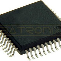
MC908AP32ACFBER Freescale Semiconductor, MC908AP32ACFBER Datasheet - Page 215

MC908AP32ACFBER
Manufacturer Part Number
MC908AP32ACFBER
Description
IC MCU 32K FLASH 8MHZ 44-QFP
Manufacturer
Freescale Semiconductor
Series
HC08r
Datasheet
1.MC908AP16ACFBER.pdf
(316 pages)
Specifications of MC908AP32ACFBER
Core Processor
HC08
Core Size
8-Bit
Speed
8MHz
Connectivity
I²C, IRSCI, SCI, SPI
Peripherals
LED, LVD, POR, PWM
Number Of I /o
32
Program Memory Size
32KB (32K x 8)
Program Memory Type
FLASH
Ram Size
2K x 8
Voltage - Supply (vcc/vdd)
4.5 V ~ 5.5 V
Data Converters
A/D 8x10b
Oscillator Type
Internal
Operating Temperature
-40°C ~ 85°C
Package / Case
44-QFP
Processor Series
HC08AP
Core
HC08
Data Bus Width
8 bit
Data Ram Size
2 KB
Interface Type
SCI, SPI
Maximum Clock Frequency
8 MHz
Number Of Programmable I/os
32
Number Of Timers
4
Maximum Operating Temperature
+ 85 C
Mounting Style
SMD/SMT
Development Tools By Supplier
FSICEBASE, DEMO908AP64E, M68CBL05CE
Minimum Operating Temperature
- 40 C
On-chip Adc
10 bit, 8 Channel
Lead Free Status / RoHS Status
Lead free / RoHS Compliant
Eeprom Size
-
Lead Free Status / Rohs Status
Details
Available stocks
Company
Part Number
Manufacturer
Quantity
Price
Company:
Part Number:
MC908AP32ACFBER
Manufacturer:
Freescale Semiconductor
Quantity:
10 000
- Current page: 215 of 316
- Download datasheet (2Mb)
13.7.1 Overflow Error
The overflow flag (OVRF) becomes set if the receive data register still has unread data from a previous
transmission when the capture strobe of bit 1 of the next transmission occurs. The bit 1 capture strobe
occurs in the middle of SPSCK cycle 7. (See
received after the overflow and before the OVRF bit is cleared does not transfer to the receive data
register and does not set the SPI receiver full bit (SPRF). The unread data that transferred to the receive
data register before the overflow occurred can still be read. Therefore, an overflow error always indicates
the loss of data. Clear the overflow flag by reading the SPI status and control register and then reading
the SPI data register.
OVRF generates a receiver/error CPU interrupt request if the error interrupt enable bit (ERRIE) is also
set. The SPRF, MODF, and OVRF interrupts share the same CPU interrupt vector. (See
It is not possible to enable MODF or OVRF individually to generate a receiver/error CPU interrupt request.
However, leaving MODFEN low prevents MODF from being set.
If the CPU SPRF interrupt is enabled and the OVRF interrupt is not, watch for an overflow condition.
Figure 13-9
possible to read the SPSCR and SPDR to clear the SPRF without problems. However, as illustrated by
the second transmission example, the OVRF bit can be set in between the time that SPSCR and SPDR
are read.
In this case, an overflow can be missed easily. Since no more SPRF interrupts can be generated until this
OVRF is serviced, it is not obvious that bytes are being lost as more transmissions are completed. To
prevent this, either enable the OVRF interrupt or do another read of the SPSCR following the read of the
SPDR. This ensures that the OVRF was not set before the SPRF was cleared and that future
transmissions can set the SPRF bit.
SPSCR read, enable the OVRF to the CPU by setting the ERRIE bit.
Freescale Semiconductor
shows how it is possible to miss an overflow. The first part of
SPSCR
OVRF
READ
READ
SPDR
SPRF
1
2
3
4
BYTE 1
BYTE 1 SETS SPRF BIT.
CPU READS SPSCR WITH SPRF BIT SET
AND OVRF BIT CLEAR.
CPU READS BYTE 1 IN SPDR,
CLEARING SPRF BIT.
BYTE 2 SETS SPRF BIT.
1
2
Figure 13-9. Missed Read of Overflow Condition
3
MC68HC908AP A-Family Data Sheet, Rev. 3
Figure 13-10
BYTE 2
4
Figure 13-4
illustrates this process. Generally, to avoid this second
BYTE 3
5
5
6
7
8
6
and
CPU READS SPSCR WITH SPRF BIT SET
AND OVRF BIT CLEAR.
BYTE 3 SETS OVRF BIT. BYTE 3 IS LOST.
CPU READS BYTE 2 IN SPDR, CLEARING SPRF BIT,
BUT NOT OVRF BIT.
BYTE 4 FAILS TO SET SPRF BIT BECAUSE
OVRF BIT IS NOT CLEARED. BYTE 4 IS LOST.
7
Figure
13-6.) If an overflow occurs, all data
BYTE 4
8
Figure 13-9
shows how it is
Error Conditions
Figure
13-11.)
215
Related parts for MC908AP32ACFBER
Image
Part Number
Description
Manufacturer
Datasheet
Request
R
Part Number:
Description:
Manufacturer:
Freescale Semiconductor, Inc
Datasheet:
Part Number:
Description:
Manufacturer:
Freescale Semiconductor, Inc
Datasheet:
Part Number:
Description:
Manufacturer:
Freescale Semiconductor, Inc
Datasheet:
Part Number:
Description:
Manufacturer:
Freescale Semiconductor, Inc
Datasheet:
Part Number:
Description:
Manufacturer:
Freescale Semiconductor, Inc
Datasheet:
Part Number:
Description:
Manufacturer:
Freescale Semiconductor, Inc
Datasheet:
Part Number:
Description:
Manufacturer:
Freescale Semiconductor, Inc
Datasheet:
Part Number:
Description:
Manufacturer:
Freescale Semiconductor, Inc
Datasheet:
Part Number:
Description:
Manufacturer:
Freescale Semiconductor, Inc
Datasheet:
Part Number:
Description:
Manufacturer:
Freescale Semiconductor, Inc
Datasheet:
Part Number:
Description:
Manufacturer:
Freescale Semiconductor, Inc
Datasheet:
Part Number:
Description:
Manufacturer:
Freescale Semiconductor, Inc
Datasheet:
Part Number:
Description:
Manufacturer:
Freescale Semiconductor, Inc
Datasheet:
Part Number:
Description:
Manufacturer:
Freescale Semiconductor, Inc
Datasheet:
Part Number:
Description:
Manufacturer:
Freescale Semiconductor, Inc
Datasheet:


