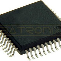
MC908AP32ACFBER Freescale Semiconductor, MC908AP32ACFBER Datasheet - Page 94

MC908AP32ACFBER
Manufacturer Part Number
MC908AP32ACFBER
Description
IC MCU 32K FLASH 8MHZ 44-QFP
Manufacturer
Freescale Semiconductor
Series
HC08r
Datasheet
1.MC908AP16ACFBER.pdf
(316 pages)
Specifications of MC908AP32ACFBER
Core Processor
HC08
Core Size
8-Bit
Speed
8MHz
Connectivity
I²C, IRSCI, SCI, SPI
Peripherals
LED, LVD, POR, PWM
Number Of I /o
32
Program Memory Size
32KB (32K x 8)
Program Memory Type
FLASH
Ram Size
2K x 8
Voltage - Supply (vcc/vdd)
4.5 V ~ 5.5 V
Data Converters
A/D 8x10b
Oscillator Type
Internal
Operating Temperature
-40°C ~ 85°C
Package / Case
44-QFP
Processor Series
HC08AP
Core
HC08
Data Bus Width
8 bit
Data Ram Size
2 KB
Interface Type
SCI, SPI
Maximum Clock Frequency
8 MHz
Number Of Programmable I/os
32
Number Of Timers
4
Maximum Operating Temperature
+ 85 C
Mounting Style
SMD/SMT
Development Tools By Supplier
FSICEBASE, DEMO908AP64E, M68CBL05CE
Minimum Operating Temperature
- 40 C
On-chip Adc
10 bit, 8 Channel
Lead Free Status / RoHS Status
Lead free / RoHS Compliant
Eeprom Size
-
Lead Free Status / Rohs Status
Details
Available stocks
Company
Part Number
Manufacturer
Quantity
Price
Company:
Part Number:
MC908AP32ACFBER
Manufacturer:
Freescale Semiconductor
Quantity:
10 000
- Current page: 94 of 316
- Download datasheet (2Mb)
Clock Generator Module (CGM)
VCO clock frequency is corrupt, and appropriate precautions should be taken. If the application is not
frequency sensitive, interrupts should be disabled to prevent PLL interrupt service routines from impeding
software performance or from exceeding stack limitations.
6.7 Special Modes
The WAIT instruction puts the MCU in low power-consumption standby modes.
6.7.1 Wait Mode
The WAIT instruction does not affect the CGM. Before entering wait mode, software can disengage and
turn off the PLL by clearing the BCS and PLLON bits in the PLL control register (PCTL) to save power.
Less power-sensitive applications can disengage the PLL without turning it off, so that the PLL clock is
immediately available at WAIT exit. This would be the case also when the PLL is to wake the MCU from
wait mode, such as when the PLL is first enabled and waiting for LOCK or LOCK is lost.
6.7.2 Stop Mode
The STOP instruction disables the PLL analog circuits and no clock will be driven out of the VCO.
When entering stop mode with the VCO clock (CGMPCLK) selected, before executing the STOP
instruction:
On exit from stop mode:
6.7.3 CGM During Break Interrupts
The system integration module (SIM) controls whether status bits in other modules can be cleared during
the break state. The BCFE bit in the SIM break flag control register (SBFCR) enables software to clear
status bits during the break state. (See
To allow software to clear status bits during a break interrupt, write a logic 1 to the BCFE bit. If a status
bit is cleared during the break state, it remains cleared when the MCU exits the break state.
To protect the PLLF bit during the break state, write a logic 0 to the BCFE bit. With BCFE at logic 0 (its
default state), software can read and write the PLL control register during the break state without affecting
the PLLF bit.
94
1. Set the oscillator stop mode enable bit (STOP_XCLKEN in CONFIG2) if continuos clock is required
2. Clear the BCS bit to select CGMXCLK as CGMOUT.
1. Set the PLLON bit if cleared before entering stop mode.
2. Wait for PLL to lock by checking the LOCK bit.
3. Set BCS bit to select CGMPCLK as CGMOUT.
in stop mode.
Software can select the CGMPCLK divided by two as the CGMOUT source
even if the PLL is not locked (LOCK = 0). Therefore, software should make
sure the PLL is locked before setting the BCS bit.
MC68HC908AP A-Family Data Sheet, Rev. 3
7.7.3 SIM Break Flag Control
NOTE
Register.)
Freescale Semiconductor
Related parts for MC908AP32ACFBER
Image
Part Number
Description
Manufacturer
Datasheet
Request
R
Part Number:
Description:
Manufacturer:
Freescale Semiconductor, Inc
Datasheet:
Part Number:
Description:
Manufacturer:
Freescale Semiconductor, Inc
Datasheet:
Part Number:
Description:
Manufacturer:
Freescale Semiconductor, Inc
Datasheet:
Part Number:
Description:
Manufacturer:
Freescale Semiconductor, Inc
Datasheet:
Part Number:
Description:
Manufacturer:
Freescale Semiconductor, Inc
Datasheet:
Part Number:
Description:
Manufacturer:
Freescale Semiconductor, Inc
Datasheet:
Part Number:
Description:
Manufacturer:
Freescale Semiconductor, Inc
Datasheet:
Part Number:
Description:
Manufacturer:
Freescale Semiconductor, Inc
Datasheet:
Part Number:
Description:
Manufacturer:
Freescale Semiconductor, Inc
Datasheet:
Part Number:
Description:
Manufacturer:
Freescale Semiconductor, Inc
Datasheet:
Part Number:
Description:
Manufacturer:
Freescale Semiconductor, Inc
Datasheet:
Part Number:
Description:
Manufacturer:
Freescale Semiconductor, Inc
Datasheet:
Part Number:
Description:
Manufacturer:
Freescale Semiconductor, Inc
Datasheet:
Part Number:
Description:
Manufacturer:
Freescale Semiconductor, Inc
Datasheet:
Part Number:
Description:
Manufacturer:
Freescale Semiconductor, Inc
Datasheet:


