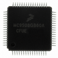
MC9S08GB60ACFUE Freescale Semiconductor, MC9S08GB60ACFUE Datasheet - Page 12

MC9S08GB60ACFUE
Manufacturer Part Number
MC9S08GB60ACFUE
Description
IC MCU 60K FLASH 4K RAM 64-LQFP
Manufacturer
Freescale Semiconductor
Series
HCS08r
Datasheet
1.MC9S08GT60ACFDER.pdf
(302 pages)
Specifications of MC9S08GB60ACFUE
Core Processor
HCS08
Core Size
8-Bit
Speed
40MHz
Connectivity
I²C, SCI, SPI
Peripherals
LVD, POR, PWM, WDT
Number Of I /o
56
Program Memory Size
60KB (60K x 8)
Program Memory Type
FLASH
Ram Size
4K x 8
Voltage - Supply (vcc/vdd)
1.8 V ~ 3.6 V
Data Converters
A/D 8x10b
Oscillator Type
Internal
Operating Temperature
-40°C ~ 85°C
Package / Case
64-LQFP
Processor Series
S08GB
Core
HCS08
Data Bus Width
8 bit
Data Ram Size
4 KB
Interface Type
SCI/SPI
Maximum Clock Frequency
40 MHz
Number Of Programmable I/os
56
Number Of Timers
8
Operating Supply Voltage
0 V to 1.8 V
Maximum Operating Temperature
+ 85 C
Mounting Style
SMD/SMT
3rd Party Development Tools
EWS08
Development Tools By Supplier
M68EVB908GB60E, M68DEMO908GB60E
Minimum Operating Temperature
- 40 C
On-chip Adc
8-ch x 10-bit
For Use With
M68DEMO908GB60E - BOARD DEMO MC9S08GB60M68EVB908GB60E - BOARD EVAL FOR MC9S08GB60
Lead Free Status / RoHS Status
Lead free / RoHS Compliant
Eeprom Size
-
Lead Free Status / Rohs Status
Lead free / RoHS Compliant
Available stocks
Company
Part Number
Manufacturer
Quantity
Price
Company:
Part Number:
MC9S08GB60ACFUE
Manufacturer:
EM
Quantity:
12 000
Company:
Part Number:
MC9S08GB60ACFUE
Manufacturer:
FREESCAL
Quantity:
1 045
Company:
Part Number:
MC9S08GB60ACFUE
Manufacturer:
Freescale Semiconductor
Quantity:
10 000
Part Number:
MC9S08GB60ACFUE
Manufacturer:
FREESCALE
Quantity:
20 000
Company:
Part Number:
MC9S08GB60ACFUER
Manufacturer:
Freescale Semiconductor
Quantity:
10 000
Section Number
10.6 TPM Interrupts ..............................................................................................................................163
10.7 TPM Registers and Control Bits ...................................................................................................164
11.1 Introduction ...................................................................................................................................171
11.2 Register Definition ........................................................................................................................176
11.3 Functional Description ..................................................................................................................183
12
10.5.1 Counter ..........................................................................................................................159
10.5.2 Channel Mode Selection ................................................................................................160
10.5.3 Center-Aligned PWM Mode ..........................................................................................161
10.6.1 Clearing Timer Interrupt Flags ......................................................................................163
10.6.2 Timer Overflow Interrupt Description ...........................................................................163
10.6.3 Channel Event Interrupt Description .............................................................................163
10.6.4 PWM End-of-Duty-Cycle Events ..................................................................................164
10.7.1 Timer x Status and Control Register (TPMxSC) ...........................................................165
10.7.2 Timer x Counter Registers (TPMxCNTH:TPMxCNTL) ..............................................166
10.7.3 Timer x Counter Modulo Registers (TPMxMODH:TPMxMODL) ..............................167
10.7.4 Timer x Channel n Status and Control Register (TPMxCnSC) .....................................168
10.7.5 Timer x Channel Value Registers (TPMxCnVH:TPMxCnVL) .....................................169
11.1.1 Features ..........................................................................................................................173
11.1.2 Modes of Operation .......................................................................................................173
11.1.3 Block Diagram ...............................................................................................................174
11.2.1 SCI Baud Rate Registers (SCIxBDH, SCIxBHL) .........................................................176
11.2.2 SCI Control Register 1 (SCIxC1) ..................................................................................177
11.2.3 SCI Control Register 2 (SCIxC2) ..................................................................................178
11.2.4 SCI Status Register 1 (SCIxS1) .....................................................................................179
11.2.5 SCI Status Register 2 (SCIxS2) .....................................................................................181
11.2.6 SCI Control Register 3 (SCIxC3) ..................................................................................181
11.2.7 SCI Data Register (SCIxD) ...........................................................................................182
11.3.1 Baud Rate Generation ....................................................................................................183
11.3.2 Transmitter Functional Description ...............................................................................183
11.3.3 Receiver Functional Description ...................................................................................184
11.3.4 Interrupts and Status Flags .............................................................................................186
11.3.5 Additional SCI Functions ..............................................................................................187
10.5.2.1 Input Capture Mode ......................................................................................160
10.5.2.2 Output Compare Mode .................................................................................160
10.5.2.3 Edge-Aligned PWM Mode ...........................................................................160
11.3.2.1 Send Break and Queued Idle ........................................................................184
11.3.3.1 Data Sampling Technique .............................................................................185
11.3.3.2 Receiver Wakeup Operation .........................................................................185
11.3.5.1 8- and 9-Bit Data Modes ...............................................................................187
11.3.5.2 Stop Mode Operation ....................................................................................187
11.3.5.3 Loop Mode ....................................................................................................188
Serial Communications Interface (S08SCIV1)
MC9S08GB60A Data Sheet, Rev. 2
Chapter 11
Title
Freescale Semiconductor
Page


