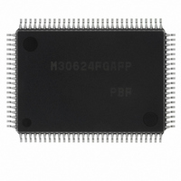
M30624FGAFP#U3 Renesas Electronics America, M30624FGAFP#U3 Datasheet - Page 394

M30624FGAFP#U3
Manufacturer Part Number
M30624FGAFP#U3
Description
IC M16C MCU FLASH 100QFP
Manufacturer
Renesas Electronics America
Series
M16C™ M16C/60r
Datasheets
1.M30622SAFPU5.pdf
(277 pages)
2.M30622SAFPU5.pdf
(617 pages)
3.M30622SAFPU5.pdf
(308 pages)
Specifications of M30624FGAFP#U3
Core Processor
M16C/60
Core Size
16-Bit
Speed
16MHz
Connectivity
SIO, UART/USART
Peripherals
DMA, PWM, WDT
Number Of I /o
85
Program Memory Size
256KB (256K x 8)
Program Memory Type
FLASH
Ram Size
20K x 8
Voltage - Supply (vcc/vdd)
4.2 V ~ 5.5 V
Data Converters
A/D 10x10b, D/A 2x8b
Oscillator Type
Internal
Operating Temperature
-40°C ~ 85°C
Package / Case
100-QFP
For Use With
867-1000 - KIT QUICK START RENESAS 62PM3062PT3-CPE-3 - EMULATOR COMPACT M16C/62P/30P
Lead Free Status / RoHS Status
Lead free / RoHS Compliant
Eeprom Size
-
Available stocks
Company
Part Number
Manufacturer
Quantity
Price
Part Number:
M30624FGAFP#U3M30624FGAFP#D3
Manufacturer:
Renesas Electronics America
Quantity:
10 000
Part Number:
M30624FGAFP#U3M30624FGAFP#D5
Manufacturer:
Renesas Electronics America
Quantity:
10 000
- Current page: 394 of 617
- Download datasheet (9Mb)
UART
Table 2.5.2. Example of baud rate setting
Table 2.5.3. Error detection
Framing error
Parity error
Error-sum flag
Overrun error
(2) Transfer rate
Baud rate
(3) An error detection
Type of error
(bps)
The divide-by-16 frequency, resulting from division in the bit rate generator (BRG), becomes the trans-
fer rate. The count source for the transfer rate register can be selected from f
from the CLK pin. Clocks f
respectively.
In clock-asynchronous serial I/O mode, detect errors are shown in Table 2.5.3.
14400
19200
28800
31250
1200
2400
4800
9600
600
count source
BRG's
f
f
f
f
f
f
f
f
f
• With parity enabled, this error
• This error occurs when the
• The next data is written to the
• The UARTi receive interrupt
• This error occurs when the
• This flag turns on when any
8
8
8
1
1
1
1
1
1
occurs when the total number
of 1's in character bits and the
parity bit is different from the
specified number.
next data lines up before the
content of the UARTi receive
buffer register is read.
UARTi receive buffer register.
request bit does not change.
stop bit falls short of the set
number of stop bits.
error (overrun, framing, or
parity) is detected.
Description
1
BRG's set value : n
, f
8
, f
207 (CF
207 (CF
103 (67
103 (67
51 (33
68 (44
51 (33
34 (22
33 (21
32
System clock : 16MHz
are derived by dividing the CPU’s main clock by 1, 8, and 32
16
16
16
16
16
16
16
16
16
)
)
)
)
)
)
)
)
)
Actual time (bps)
When the flag turns on
The error is detected
when data is
transferred from the
UARTi receive register
to the UARTi receive
buffer register.
14493
19231
28571
31250
1202
2404
4808
9615
601
SINGLE-CHIP 16-BIT CMOS MICROCOMPUTER
BRG's set value : n
95 (5F
47 (2F
95 (5F
47 (2F
31 (1F
15 (F
23 (17
23 (17
• Set the serial I/O mode select
• Set the receive enable bit to
• Set the serial I/O mode select
• Set the receive enable bit to
• Read the lower-order byte of
• When all error (overrun,
System clock : 7.3728MHz
bits to “000
“0”.
framing, and parity) are
removed, the flag is cleared.
bits to ”000
“0”.
the UARTi receive buffer
register.
16
16
16
16
16
16
16
16
How to clear the flag
)
)
)
)
)
)
)
)
1
, f
8
M16C / 62A Group
, f
2
2
”.
Mitsubishi microcomputers
”.
32
Actual time (bps)
, and the input
14400
19200
28800
1200
2400
4800
9600
600
2-75
Related parts for M30624FGAFP#U3
Image
Part Number
Description
Manufacturer
Datasheet
Request
R

Part Number:
Description:
KIT STARTER FOR M16C/29
Manufacturer:
Renesas Electronics America
Datasheet:

Part Number:
Description:
KIT STARTER FOR R8C/2D
Manufacturer:
Renesas Electronics America
Datasheet:

Part Number:
Description:
R0K33062P STARTER KIT
Manufacturer:
Renesas Electronics America
Datasheet:

Part Number:
Description:
KIT STARTER FOR R8C/23 E8A
Manufacturer:
Renesas Electronics America
Datasheet:

Part Number:
Description:
KIT STARTER FOR R8C/25
Manufacturer:
Renesas Electronics America
Datasheet:

Part Number:
Description:
KIT STARTER H8S2456 SHARPE DSPLY
Manufacturer:
Renesas Electronics America
Datasheet:

Part Number:
Description:
KIT STARTER FOR R8C38C
Manufacturer:
Renesas Electronics America
Datasheet:

Part Number:
Description:
KIT STARTER FOR R8C35C
Manufacturer:
Renesas Electronics America
Datasheet:

Part Number:
Description:
KIT STARTER FOR R8CL3AC+LCD APPS
Manufacturer:
Renesas Electronics America
Datasheet:

Part Number:
Description:
KIT STARTER FOR RX610
Manufacturer:
Renesas Electronics America
Datasheet:

Part Number:
Description:
KIT STARTER FOR R32C/118
Manufacturer:
Renesas Electronics America
Datasheet:

Part Number:
Description:
KIT DEV RSK-R8C/26-29
Manufacturer:
Renesas Electronics America
Datasheet:

Part Number:
Description:
KIT STARTER FOR SH7124
Manufacturer:
Renesas Electronics America
Datasheet:

Part Number:
Description:
KIT STARTER FOR H8SX/1622
Manufacturer:
Renesas Electronics America
Datasheet:

Part Number:
Description:
KIT DEV FOR SH7203
Manufacturer:
Renesas Electronics America
Datasheet:


