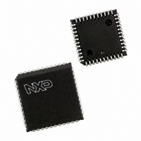
PXAC37KFA/00,512 NXP Semiconductors, PXAC37KFA/00,512 Datasheet - Page 19

PXAC37KFA/00,512
Manufacturer Part Number
PXAC37KFA/00,512
Description
IC XA MCU 16BIT 32K OTP 44-PLCC
Manufacturer
NXP Semiconductors
Series
XAr
Datasheet
1.PXAC37KFA00512.pdf
(68 pages)
Specifications of PXAC37KFA/00,512
Core Processor
XA
Core Size
16-Bit
Speed
32MHz
Connectivity
CAN, EBI/EMI, SPI, UART/USART
Peripherals
DMA, POR, PWM, WDT
Number Of I /o
32
Program Memory Size
32KB (32K x 8)
Program Memory Type
OTP
Ram Size
1K x 8
Voltage - Supply (vcc/vdd)
4.5 V ~ 5.5 V
Oscillator Type
External
Operating Temperature
-40°C ~ 85°C
Package / Case
44-PLCC
Lead Free Status / RoHS Status
Lead free / RoHS Compliant
Eeprom Size
-
Data Converters
-
Other names
568-3533-5
935266516512
PXAC37KFA
935266516512
PXAC37KFA
Available stocks
Company
Part Number
Manufacturer
Quantity
Price
Company:
Part Number:
PXAC37KFA/00,512
Manufacturer:
NXP Semiconductors
Quantity:
10 000
Philips Semiconductors
XA-C3 TIMER/COUNTERS
The XA has two standard 16–bit enhanced Timer/Counters: Timer 0
and Timer 1. Additionally, it has a third 16–bit Up/Down
timer/counter, T2. A central timing generator in the XA core provides
the time–base for all XA Timers and Counters. The timer/event
counters can perform the following functions:
– Measure time intervals and pulse duration
– Count External events
– Generate interrupt requests
– Generate PWM or timed output waveforms
All timer/counters (Timer 0, Timer 1 and Timer 2) can be
independently programmed to operate either as timers or event
counters. Timer 0 and Timer 1 are selectable via TMOD[6] and
TMOD[2], respectively. Timer 2 is selectable via T2CON[1]. All
timers may be dynamically read during program execution. All timers
count up unless otherwise stated.
When running in timer mode (as opposed to counter mode) the base
clock rate of all timers, including the Watchdog timer, is
user–programmable. The clock driving the timers is called TCLK
and is determined by the setting of two bits (PT1, PT0) (SCR[3:2]) in
the System Configuration Register – See Table 5. The frequency of
TCLK may be selected to be the oscillator input divided by 4 (f c /4),
2000 Jan 25
XA 16-bit microcontroller family
32K/1024 OTP CAN transport layer controller
1 UART, 1 SPI Port, CAN 2.0B, 32 CAN ID filters, transport layer co-processor
TMOD
Not Bit Addressable
Reset Value: 00H
SCR
Not Bit Addressable
Reset Value: 00H
PT1
0
0
1
1
CM
PZ
M1
0
0
1
1
Address:45C
Address:440
PT0
0
1
0
1
GATE
C/T
M0
0
1
0
1
OPERATING
Prescaler selection.
Osc/4
Osc/16
Osc/64
Reserved
Compatibility Mode allows the XA to execute most translated 80C51 code on the XA. The
XA register file must copy the 80C51 mapping to data memory and mimic the 80C51 indirect
addressing scheme.
Page Zero mode forces all program and data addresses to 16-bits only. This saves stack space
and speeds up execution but limits memory access to 64k.
Gating control when set. Timer/Counter “n” is enabled only while “INTn” pin is high and
“TRn” control bit is set. When cleared Timer “n” is enabled whenever “TRn” control bit is set.
Timer or Counter Selector cleared for Timer operation (input from internal system clock.)
Set for Counter operation (input from “Tn” input pin).
OPERATING
16-bit auto-reload timer/counter
16-bit non-auto-reload timer/counter
8-bit auto-reload timer/counter
Dual 8-bit timer mode (timer 0 only)
MSB
MSB
GATE
Figure 6. Timer/Counter Mode Control (TMOD) Register
—
Figure 5. System Configuration Register (SCR)
C1 or
T1/
—
TIMER 1
M1
—
M0
—
12
GATE
PT1
the oscillator input divided by 16 (f c /16), or the oscillator input
divided by 64 (f c /64). This gives a range of possibilities for the XA
timer functions, including baud rate generation and Timer 2 capture.
Note: This single SCR rate setting applies to all timers.
When timers T0, T1, or T2 are used in the counter mode, the timers
will increment whenever a falling edge (high–to–low transition) is
detected on an External clock pin. These inputs are sampled once
every two oscillator cycles, so it can take as many as four oscillator
cycles to detect a transition. Thus, the maximum count rate that can
be supported is f c /4. In general, the duty cycle of the timer clock
inputs is not important. However, any high or low state on the timer
clock input pins must be present for two oscillator cycles before it is
guaranteed to be “seen” by the timer logic.
Timer 0 and Timer 1
These two Timer/Counters have four operating modes, which are
selected by bit–pairs (M1, M0) in the TMOD register. Timer modes
1, 2, and 3 in XA are kept identical to the 80C51 timer modes for
code compatibility. Only the mode 0 is replaced in the XA by a more
powerful 16–bit auto–reload mode. This gives the XA timers a much
larger range when used as time bases.
The recommended M1, M0 settings for the different modes are
shown in Figure 6.
C0 or
PT0
T0/
TIMER 0
CM
M1
M0
PZ
LSB
LSB
SU01325
Preliminary specification
SU00589
XA-C3


