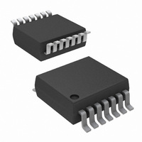
EL5411IRZ-T13 Intersil, EL5411IRZ-T13 Datasheet - Page 12

EL5411IRZ-T13
Manufacturer Part Number
EL5411IRZ-T13
Description
IC OP AMP QUAD 60MHZ RR 14-TSSOP
Manufacturer
Intersil
Datasheet
1.EL5111IWTZ-T7A.pdf
(18 pages)
Specifications of EL5411IRZ-T13
Amplifier Type
Voltage Feedback
Number Of Circuits
4
Output Type
Rail-to-Rail
Slew Rate
75 V/µs
Gain Bandwidth Product
32MHz
-3db Bandwidth
60MHz
Current - Input Bias
2nA
Voltage - Input Offset
3000µV
Current - Supply
10mA
Current - Output / Channel
65mA
Voltage - Supply, Single/dual (±)
4.5 V ~ 16.5 V, ±2.25 V ~ 8.25 V
Operating Temperature
-40°C ~ 85°C
Mounting Type
Surface Mount
Package / Case
14-TSSOP
Lead Free Status / RoHS Status
Lead free / RoHS Compliant
The maximum power dissipation actually produced by an IC
is the total quiescent supply current times the total power
supply voltage, plus the power in the IC due to the loads, or:
P
when sourcing, and:
P
when sinking,
where:
• i = 1 to 2 for dual and 1 to 4 for quad
• V
• I
• V
• I
If we set the two P
can solve for R
through 36 provide a convenient way to see if the device will
overheat. The maximum safe power dissipation can be
found graphically, based on the package type and the
ambient temperature. By using the previous equation, it is a
simple matter to see if P
derating curves. To ensure proper operation, it is important
to observe the recommended derating curves shown in
Figures 29 through 36.
DMAX
DMAX
FIGURE 29. PACKAGE POWER DISSIPATION vs AMBIENT
SMAX
LOAD
S
OUT
= Total supply voltage
=
=
i = Maximum output voltage of the application
i = Load current
= Maximum supply current per amplifier
0.9
0.8
0.7
0.6
0.5
0.4
0.3
0.2
0.1
0.0
Σi V
Σi V
[
[
0
JEDEC JESD51-3 LOW EFFECTIVE THERMAL
CONDUCTIVITY TEST BOARD
TEMPERATURE
694mW
S
S
LOAD
×
×
I
I
SMAX
SMAX
DMAX
25
AMBIENT TEMPERATURE (°C)
i to avoid device overheat. Figures 29
+
+
DMAX
equations equal to each other, we
(
(
V
V
θ
50
JA
S
OUT
12
HTSSOP14
+ V
= +144°C/W
exceeds the device's power
–
i V
–
OUT
75
S
- ) I
i )
85
×
×
I
LOAD
LOAD
100
i
EL5111, EL5211, EL5411
i
]
]
125
(EQ. 2)
(EQ. 3)
FIGURE 30. PACKAGE POWER DISSIPATION vs AMBIENT
FIGURE 31. PACKAGE POWER DISSIPATION vs AMBIENT
FIGURE 32. PACKAGE POWER DISSIPATION vs AMBIENT
3.5
3.0
2.5
2.0
1.5
1.0
0.5
0.0
1.2
1.0
0.8
0.6
0.4
0.2
0.0
1.8
1.6
1.4
1.2
1.0
0.8
0.6
0.4
0.2
0.0
0
0
0
JEDEC JESD51-7 HIGH EFFECTIVE THERMAL
CONDUCTIVITY TEST BOARD
JEDEC JESD51-7 HIGH EFFECTIVE THERMAL
CONDUCTIVITY (4-LAYER) TEST BOARD -
HTSSOP EXPOSED DIEPAD SOLDERED TO
PCB PER JESD51-5
JEDEC JESD51-3 LOW EFFECTIVE THERMAL
CONDUCTIVITY TEST BOARD
TEMPERATURE
TEMPERATURE
TEMPERATURE
2.632W
977mW
893mW
845mW
758mW
1.667W
1.471W
1.389W
1.289W
1.250W
1.042W
25
25
25
AMBIENT TEMPERATURE (°C)
AMBIENT TEMPERATURE (°C)
AMBIENT TEMPERATURE (°C)
50
50
50
θ
JA
75
75
HTSSOP14
= +38°C/W
85
85
75
θ
θ
θ
θ
θ
100
100
θ
JA
JA
JA
JA
JA
θ
θ
θ
θ
85
JA
JA
JA
JA
JA
TSSOP28
TSSOP24
TSSOP20
TSSOP16
TSSOP14
TSSOP28
TSSOP24
TSSOP20
TSSOP16
TSSOP14
= +120°C/W
= +128°C/W
= +140°C/W
= +148°C/W
= +165°C/W
=+100°C/W
=+75°C/W
=+85°C/W
=+90°C/W
=+97°C/W
100
125
125
125
150
150
May 7, 2007
FN7119.7


