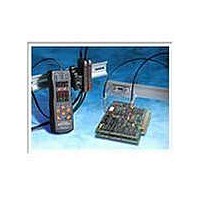
E3X-DA14V Omron, E3X-DA14V Datasheet - Page 23

E3X-DA14V
Manufacturer Part Number
E3X-DA14V
Description
DIGTL NPN NANO CONN READY MDL
Manufacturer
Omron
Series
E3X-DA-Nr
Datasheet
1.E3X-DA6.pdf
(36 pages)
Specifications of E3X-DA14V
Amplifier Type
Water Resistant
Voltage - Supply
12 V ~ 24 V
Output Type
NPN
Current - Supply
40mA
Mounting Type
DIN Rail
Lead Free Status / RoHS Status
Lead free / RoHS Compliant
Lead Free Status / RoHS Status
Lead free / RoHS Compliant, Lead free / RoHS Compliant
Other names
E3XDA14V
Safety Precautions
This product is not designed or rated for
ensuring safety of persons. Do not use it for
such purpose.
Do not use the product in atmospheres or environments that
exceed product ratings.
Amplifiers
● Designing
Operation after Turning Power ON
The Sensor is ready to detect within 200 ms after the power
supply is turned ON. If the Sensor and load are connected to
separate power supplies, be sure to turn ON the Sensor first.
● Mounting
Joining and Separating Amplifiers
Joining Amplifiers
(1) Mount the Amplifiers one at a time onto the DIN track.
(2) Slide the Amplifiers together, line up the clips, and press
Separating Amplifiers
Slide Amplifiers away from each other, and remove from the
DIN track one at a time. (Do not attempt to remove Amplifiers
from the DIN track without separating them first.)
Note 1. The specifications for ambient temperature will vary according to the
the Amplifiers together until they click into place.
2. Always turn OFF the power supply before joining or separating
number of Amplifiers used together. For details, refer to Ratings and
Specifications.
Amplifiers.
Clip
Precautions for Correct Use
http://www.ia.omron.com/
WARNING
into place
Click
Fiber Connection and Disconnection
The E3X Amplifier uses a one-touch locking mechanism.
(Only the E3X-NM uses a locking button mechanism.)
Connect or disconnect the fibers to or from the E3X Amplifier
using the following procedures:
(1) Connection
Open the protective cover, insert the fibers according to the
fiber insertion marks on the side of the Amplifier, and lower the
lock button.
(2) Disconnection
Remove the protective
cover and raise the
lock button to pull out
the fiber.
Note: To maintain the fiber properties, confirm that the
(3) Precautions for Fiber Connection/Disconnection
Be sure to lock or unlock the lock button within an ambient
temperature range between −10 and 40°C.
Mounting the Mobile Console Head
Leave a gap of at least 20 mm
between the nearest Amplifier and
the Mobile Console head.
Mounting the Mobile Console Head
With Twin-output models (E3X-DA@@TW), up to 16 channels
(i.e., eight E3X-DA@@TW Amplifiers) can be set using the
E3X-MC11 Mobile Console. (Operating modes and area
detection, however, cannot be set.)
● Adjustment
Mutual Interference Protection Function
There may be some instability in the digital display values due
to light from other sensors. If this occurs, decrease the
sensitivity (i.e., increase the threshold) to perform stable
detection.
EEPROM Writing Error
If the data is not written to the EEPROM correctly due to a
power failure during teaching or static-electric noise, repeat
the whole teaching procedure.
Lock button
Fiber
lock is released before removing the fiber.
(c)Copyright OMRON Corporation 2007 All Rights Reserved.
Fiber insertion
mark
Locked
10.7 mm
Unlocked
Insertion position
E3X-DA-N
20 mm
Protective cover
23


