STM32L152-EVAL STMicroelectronics, STM32L152-EVAL Datasheet
STM32L152-EVAL
Specifications of STM32L152-EVAL


Related parts for STM32L152-EVAL


STM32L152-EVAL Summary of contents
Page 1
... Introduction The STM32L152-EVAL evaluation board is a complete demonstration and development platform for STMicroelectronics’ ARM cortex-M3 core-based STM32L152VBT6 microcontroller supporting two I2C, two SPI and three USART channels, 12-bit ADC, 12-bit DAC internal SRAM and 128 KB Flash, USB FS, LCD controller, touch sensing and JTAG debugging support ...
Page 2
Contents Contents 1 Features . . . . . . . . . . . . . . . . . . . . . . . . . . . . . . . . . . . . ...
Page 3
UM1018 3.7 User USB Type B connector CN1 . . . . . . . . . . . . . . . . . . . . . . . . . . . . . . 24 3.8 ...
Page 4
... Demonstration software is preloaded in the board's Flash memory for easy demonstration of the device peripherals in stand-alone mode. For more information and to download the latest version available, please refer to the STM32L152-EVAL demonstration software available on www.st.com. 1.2 Order code To order the STM32L152VBT6 evaluation board, use the order code STM32L152-EVAL. 4/44 TM Doc ID 18141 Rev 1 UM1018 ...
Page 5
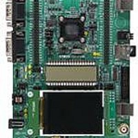
... UM1018 2 Hardware and layout The STM32L152-EVAL evaluation board is designed around the STM32L152VBT6 microcontroller in a 100-pin TQFP package. Figure 1 illustrates the connections between the STM32L152VBT6 and its peripherals (color LCD, touch sensing button, USB FS connector, temperature sensor, USART, IrDA, audio, MicroSD Card and embedded ST-LINK/V2). ...
Page 6
... Hardware and layout Figure 2. STM32L152-EVAL board layout CN6, CN7 Extension header CN2 UART2 U11 STM32L152VBT6 CN5 UART3 U17 IrDA CN14 Color LCD CN12 power jack RV2 VDD_adjustment RV3 potentiometer 6/44 VDD range LEDs indicator 4 color LEDs B1 reset key Doc ID 18141 Rev 1 UM1018 TS1 & ...
Page 7
... CN8 (trace) or CN9 (external JTAG and SWD). 2.2 Power supply The STM32L152-EVAL is designed to be powered power supply and to be protected by PolyZen from a wrong power plug-in event possible to configure the evaluation board to use any of the following four power supply sources by setting jumpers JP12, JP13 and JP4 (see ● ...
Page 8
... For power supply from USB (CN1) to STM32L152-EVAL only, JP12 is set as shown. For power supply from USB connector of ST-LINK/V2 (CN11) to STM32L152-EVAL only, JP12 is set as shown (default setting). For power supply from power supply jack (CN12) to both STM32L152-EVAL and daughterboard connected on CN6 and CN7, JP12 is set as shown (daughterboard must not have its own power supply connected) ...
Page 9
... Table 3. 8 MHz crystal X2 related solder bridges Solder bridge SB2 SB3 2.4 Reset source The reset signal of STM32L152-EVAL evaluation board is low active and the reset sources include: ● Reset button B1 ● Debugging Tools from JTAG connector CN9 and trace connector CN8 ● ...
Page 10
... Boot0 related jumper JP6 Jumper JP6 2.6 LCD glass module An LCD glass module, U20, with 8-digit liquid crystal display is mounted on the STM32L152-EVAL evaluation board connected to the LCD controller of STM32L152VBT6. Table 6. LCD glass related jumpers Jumper PC10 is connected to LCD glass as SEG40 when JP7 is set as shown (default setting) ...
Page 11
... Speaker amplifier U27 is disabled when JP16 is closed. 2.8 USB The STM32L152-EVAL evaluation board supports USB 2.0 compliant full speed communication via a USB type B connector (CN1). The evaluation board can be powered by this USB connection with 500 mA current limitation. USB disconnection simulation can be implemented by controlling the internal 1.5 K pull-up resistor on the USB D+ line to detect 5 V power on the USB connector, CN1 (using the resistor bridge that is connected to PE5) ...
Page 12
... JP7,JP8 Refer to JP6 See Table 5 2.10 Touch sensing buttons The STM32L152-EVAL evaluation board supports two touch sensing buttons based on either charge transfer technology (default charging. RC charging technology can be enabled by modifying the board: 1. Remove R29. 2. Mount resistors R22 (1 MOhm), R23 (1 MOhm), R24 (10 KOhm) and C18(1 nF). ...
Page 13
... Comparator non-inverting input PB5 connected to potentiometer (RV3) used as analogue voltage input for comparison with internal voltage reference (for instance Band gap) in order to test analogue Wakeup feature of the MCU. Figure 3. STM32L152-EVAL comparator features Jumper JP17 allows 3 different usages of the potentiometer as shown in Table 10. Comparator and potentiometer related jumpers Jumper Potentiometer RV3 is connected to ADC input PB12 ...
Page 14
... JP11 PB5 is disconnected from I2C_SMB but remains connected to COM_IN+ when JP11 is open for comparator application. 2.14 Temperature sensor A temperature sensor STLM75M2E is connected to the I2C bus of the STM32L152VBT6 through two transistors to support a wide voltage range, from 1. 3.6 V. 14/44 Description Doc ID 18141 Rev 1 ...
Page 15
... Display and input devices The display devices are: ● 2.4" color TFT LCD, connected to the SPI1 port of the STM32L152VBT6. ● 4 general purpose color LED's (LD 1,2,3,4). LD3 and LD4 are disabled by default; JP18 and JP19 must be closed to enable these two LEDs. ...
Page 16
... Hardware and layout 2.16 IDD measurement The built-in IDD measurement circuit implemented allows the consumption measurement of the STM32L152C6T6 while the MCU is in Run or Low power saving modes. For IDD measurement the circuit below is implemented on STM32L152-EVAL. Figure 4. STM32L152-EVAL IDD measurement circuit VDD_MC U JP4 ...
Page 17
... UM1018 Figure 5. STM32L152-EVAL IDD low power modes measurement timing diagram MCU mode Run IDD_CNT_EN (PB15) Q12 = LOW_POWER_EN (T4 pin 3) Q13 = IDD_WAKEUP (PC13) Q13n = disconnect filter (U7 pin 4) The principle used to measure a current when the STM32L is in Low power mode is: 1. Configure ADC to measure voltage on the IDD_Measurement pin (PA5). ...
Page 18
Hardware and layout 2.16.3 Ibias current measurement procedure In Low power mode the bias current of operational amplifier input (U10 pin 4) is not negligible compared to IDD current (typical Ibias is ~240 nA). To obtain a reliable MCU IDD ...
Page 19
UM1018 3 Connectors 3.1 RS-232 connectors (CN2, CN5) Figure 6. RS-232 connector (viewed from front) Table 13. RS-232 connector CN2 with HW flow control and ISP support Pin number 1 2 RS-232_RX (PD6) 3 RS-232_TX (PD5 GND ...
Page 20
... Connectors 3.3 Power connector (CN12) Your STM32L152-EVAL evaluation board can be powered from power supply via the external power supply jack (CN12) shown in positive. Figure 7. Power supply connector CN12 (viewed from front) 3.4 Daughterboard extension connectors (CN6 and CN7) Two 50-pin male headers CN6 and CN7 can connect a daughterboard or standard wrapping board to the STM32L152-EVAL evaluation board ...
Page 21
... CS_LCD JTRST / LDR I2C_TEMP_SCL LCD glass_SEG36 LCD glass_SEG37 LCD glass_SEG39 / TRACE_D0 Doc ID 18141 Rev 1 Connectors How to disconnect with function block on STM32L152-EVAL board JP9 open JP19 open Remove SD card from CN4 - JP17 open JP17 and JP11 open Remove R62 - - Remove LCD glass U20 ...
Page 22
... LCD glass_SEG19 IDD_CNT_EN LCD glass_SEG35 Doc ID 18141 Rev 1 How to disconnect with function block on STM32L152-EVAL board - Remove LCD glass U20 - - How to disconnect with function block on STM32L152-EVAL board - Remove LCD glass U20 Remove LCD glass U20 Remove LCD glass U20 - - - - Remove LCD glass U20 - ...
Page 23
... LCD glass_SEG2 LCD glass_SEG0 LCD glass_SEG20 LCD glass_SEG18 - Doc ID 18141 Rev 1 Connectors How to disconnect with function block on STM32L152-EVAL board Remove LCD glass U20 Remove LCD glass U20 Remove LCD glass U20 - Remove LCD glass U20 - JP17 open Remove LCD glass U20 ...
Page 24
Connectors 3.6 ST-LINK/V2 USB type B connector CN11 The USB connector, CN11, is used to connect the embedded ST-LINK/V2 to the PC for board debugging. Figure 8. USB type B connector CN11 (viewed from front) Table 17. USB type B ...
Page 25
UM1018 3.9 JTAG connector CN9 Figure 10. JTAG debugging connector CN9 (viewed from above PCB) Table 19. JTAG debugging connector CN9 Pin number 3.10 Trace debugging connector CN8 This is ...
Page 26
Connectors Table 20. Trace debugging connector CN8 (continued) Pin number 17 19 3.11 MicroSD Card connector CN4 Figure 11. MicroSD Card connector CN4 (viewed from front) Table 21. MicroSD Card connector CN4 Pin number 1 2 MicroSDcard_CS (PD7) 3 MicroSDcard_DIN(PB15) ...
Page 27
UM1018 3.12 BNC connector CN13 Figure 12. Analog input connector CN13 (viewed from bottom) Table 22. Analog input connector CN13 Pin number 1 GND 2 GND 3 GND Description Pin number 4 5 Doc ID 18141 Rev 1 Connectors Description ...
Page 28
... Schematics 4 Schematics The following schematics are listed. ● Figure 13: STM32L152-EVAL on page 29 ● Figure 14: MCU on page 30 ● Figure 15: LCD glass on page 31 ● Figure 16: Audio on page 32 ● Figure 17: Peripherals on page 33 ● Figure 18: Power on page 34 ● Figure 19: Extension connector on page 35 ● Figure 20: LCD and SD Card on page 36 ● ...
Page 29
... Figure 13. STM32L152-EVAL 1 U_LCD_Glass LCD_Glass.SCHDOC SEG[0..43] A COM[0..3] U_Audio Audio.SchDoc Audio_IN Audio_OUT U_Extension connector Extension connector.SCHDOC RESET# PH[0..2] PE[0..15] PD[0..15] PC[0..15] PB[0..15] PA[0..15] U_IDD_measurement IDD_measurement.SchDoc B IDD_Measurement IDD_WAKEUP IDD_CNT_EN U_TemSensor TemSensor.SCHDOC I2C_SMB I2C_SDA I2C_SLK U_RS232_IrDA RS232_IrDA.SCHDOC USART2/IrDA_CTS Bootloader_RESET Bootloader_BOOT0 USART2/IrDA_RX USART3_RX USART3_TX USART2/IrDA_RTS ...
Page 30
... VSS_3 JP2 28 27 VDD_4 VSS_4 11 10 VDD_MCU VDD_5 VSS_5 6 TRACE_D3 VLCD VLCD C22 Scorpio 1uF TRACE_D0 VDD_MCU TRACE_CK R78 0 R77 0 C21 C26 C24 C17 100nF 100nF 100nF 100nF Title: STM32L152-EVAL MCU Number: MB819 Rev: B.3(PCB.SCH) Date: 10/13/2010 Sheet C23 100nF D 14 ...
Page 31
... Figure 15. LCD glass 1 A SEG[0..43 SEG[0..43] U20 PD878-DP-FH-W-LV-6- COM[0..3] COM[0..3] Title: STM32L152-EVAL LCD Glass Number: MB819 Rev: B.3(PCB.SCH) Date: 10/13/2010 Sheet ...
Page 32
... C82 R98 R129 R135 2 100K 18K 680 R101 180pF R107 82K 15K C68 C73 R100 4.7uF 2.2uF C84 100K 4.7uF U25 1 KDMG15008- Speaker+ TP9 MIC_OUT 0 R75 0 PE7 Audio_IN C69 [N/A] Title: STM32L152-EVAL Audio Number: MB819 Rev: B.3(PCB.SCH) Date: 11/8/2010 Sheet ...
Page 33
... Selection PE8 R112 0 PE10 R127 0 3 DWON PE12 R118 0 1 LEFT PE11 R117 0 4 RIGHT PE9 R126 MT008-A Joystick Title: STM32L152-EVAL Peripherals Number: MB819 Rev: B.3(PCB.SCH) Date: 10/13/2010 Sheet LD8 Red A VDD<1.8V R3 510 LD7 Orange 1.8V<VDD<2.2V R1 510 LD6 Green VDD>2. 510 ...
Page 34
... Vout 2 C55 C51 1 10uF 100nF JP13 TP7 U24 VDD_ADJ LD1086D2M R94 VDD_ADJ 3 2 124[1%] Vin Vout Power Supply VDD_ADJ [1.65V to 3.6V] C52 R95 C39 10uF 40.2[1%] 1uF C63 2 100nF R56 2K2[1%] Title: STM32L152-EVAL Power Number: MB819 Rev: B.3(PCB.SCH) Date: 10/13/2010 Sheet ...
Page 35
... PC4 35 36 PA6 37 38 PA5 39 40 PA3 41 42 PA1 43 44 PC2 45 46 PC0 Header 25X2 PA[0..15] PB[0..15] PC[0..15] PD[0..15] PE[0..15] RESET# PH[0..2] Title: STM32L152-EVAL Extension Connector Number: MB819 Rev: B.3(PCB.SCH) Date: 10/13/2010 Sheet PA[0..15] PB[0..15] PC[0..15] PD[0..15] PE[0..15] RESET# PH[0.. ...
Page 36
... PJS008-2000 (SMS064FF or SMS128FF) MicroSD card CN14 2.4" LCD connector (MB542 with AM240320L8TNQW-00H SCL 3 SDI SDO 8 RESET 9 +3V3 VDD 10 VCI R91 11 GND 4K7 12 GND 13 +5V BL_VDD 14 BL_Control 15 BL_GND 16 BL_GND TFT LCD Do not fit Title: STM32L152-EVAL LCD&SDcard Number: MB819 Rev: B.3(PCB.SCH) Date: 10/13/2010 Sheet ...
Page 37
... DB9-male USART3 +3V3 [N/A] R46 1 6 RXD 2 7 TXD U17 5 SD USART2_TXD 3 TxD IrDA_RXD 4 RxD R55 1 Anode (VCC2 Cathode R60 47 6 VCC1 GND TFDU6300 IrDA C48 C44 C47 4.7uF 100nF 100nF Title: STM32L152-EVAL RS232&IrDA Number: MB819 Rev: B.3(PCB.SCH) Date: 10/13/2010 Sheet ...
Page 38
... VDD FDC606P 100nF Q11 VCC 2 15 Q12 Q13 Rtc 8 9 GND Ctc 74LV4060PW C6 R18 1nF 15K Oscillator frequency 30KHz PA5 IDD_Measurement 4 VDD PA0 IDD_WAKEUP VDD R26 10K PC13 IDD_CNT_EN R17 30K Title: STM32L152-EVAL IDD_Measurement Number: MB819 Rev: B.3(SCH.PCB) Date: 10/13/2010 Sheet ...
Page 39
... TR1 R67 R68 R73 FDN327N R63 4K7 4K7 4K7 4K7 G R62 R69 R61 TR2 FDN327N R66 4K7 U18 1 8 SDA VDD 2 7 SCL C41 OS/INT 100nF GND A2 STLM75M2E Temperature sensor Title: STM32L152-EVAL TemperatureSensor Number: MB819 Rev: B.3(PCB.SCH) Date: 10/13/2010 Sheet ...
Page 40
... VDD C49 100nF 100nF U19 1 8 VccA VccB 2 7 T_SWDIO_IN T_JTDO A2 B2 TDO/SWO 4 5 T_SWO GND DIR SN74LVC2T45DCUT T_JTMS TMS/SWDIO T_NRST RESET# T_JRST TRST T_JTDI TDI T_JTCK TCK/SWCLK Title: STM32L152-EVAL ST_LINK (JTAG only) Number: MB819 Rev: B.3(PCB.SCH) Date: 10/13/2010 Sheet JTAG ...
Page 41
... R71 0 16 R74 [N/ JTAG connector PE6 TRACE_D3 PE5 TRACE_D2 PE4 TRACE_D1 PE3 TRACE_D0 PE2 TRACE_CK Trace connector R52 R76 [N/A] [N/A] VDD VDD R82 10 [N/ R83 14 10K R84 10K 18 19 R89 10K 20 Title: STM32L152-EVAL JTAG&Trace Number: MB819 Rev: B.3(PCB.SCH) Date: 10/13/2010 Sheet ...
Page 42
... R14 R13 R29 10K 10K <----ESD resistor close to MCU pad 0 <----Touch Sensing diameter 10mm min on active shield diameter 12mm min C11 GRM3195C1H333JA01D TS1 TS2 TS_PAD TS_PAD <----Active shield C D Title: STM32L152-EVAL Touch Sensing Number: MB819 Rev: B.3(PCB.SCH) Date: 10/13/2010 Sheet ...
Page 43
UM1018 5 Revision history Table 23. Document revision history Date 13-Dec-2010 Revision 1 Initial release. Doc ID 18141 Rev 1 Revision history Changes 43/44 ...
Page 44
... Information in this document is provided solely in connection with ST products. STMicroelectronics NV and its subsidiaries (“ST”) reserve the right to make changes, corrections, modifications or improvements, to this document, and the products and services described herein at any time, without notice. All ST products are sold pursuant to ST’s terms and conditions of sale. ...