MW7IC2425NBR1 Freescale Semiconductor, MW7IC2425NBR1 Datasheet - Page 3
MW7IC2425NBR1
Manufacturer Part Number
MW7IC2425NBR1
Description
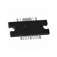
IC PWR AMP RF 2400MHZ TO-272-16
Manufacturer
Freescale Semiconductor
Datasheet
1.MW7IC2425GNR1.pdf
(21 pages)
Specifications of MW7IC2425NBR1
Current - Supply
195mA
Frequency
2.45GHz
Gain
27.7dB
Package / Case
TO-272-16
Rf Type
ISM
Test Frequency
2.45GHz
Voltage - Supply
28V
Channel Type
N
Channel Mode
Enhancement
Drain Source Voltage (max)
65V
Power Gain (typ)@vds
28.5dB
Frequency (max)
2.45GHz
Package Type
TO-272 WB EP
Pin Count
16
Output Capacitance (typ)@vds
111@28VpF
Operating Temp Range
-65C to 225C
Drain Efficiency (typ)
43.8%
Mounting
Surface Mount
Mode Of Operation
OFDM/WIMAX
Vswr (max)
10
Screening Level
Military
Lead Free Status / RoHS Status
Lead free / RoHS Compliant
Noise Figure
-
P1db
-
Lead Free Status / Rohs Status
Compliant


RF Device Data
Freescale Semiconductor
Table 5. Electrical Characteristics
Stage 2 - Off Characteristics
Stage 2 - On Characteristics
Stage 2 - Dynamic Characteristics
Narrowband Performance Specifications
I
Functional Tests
WiMAX, OFDM 802.16d, 64 QAM
measured in 1 MHz Channel Bandwidth @ ±8.5 MHz Offset.
DQ2
Zero Gate Voltage Drain Leakage Current
Zero Gate Voltage Drain Leakage Current
Gate - Source Leakage Current
Gate Threshold Voltage
Gate Quiescent Voltage
Fixture Gate Quiescent Voltage
Drain - Source On - Voltage
Output Capacitance
Power Gain
Power Added Efficiency
Input Return Loss
Power Gain
Power Added Efficiency
Output Peak - to - Average Ratio @ 0.01% Probability on CCDF
Adjacent Channel Power Ratio
Input Return Loss
1. Measured in Freescale Narrowband Test Fixture.
2. See Appendix A for functional test fixture documentation.
3. Part internally matched both on input and output.
4. Measurement made with device in straight lead configuration before any lead forming operation is applied.
(V
(V
(V
(V
(V
(V
(V
(V
= 195 mA, P
DS
DS
GS
DS
DS
DD
GS
DS
= 65 Vdc, V
= 28 Vdc, V
= 10 Vdc, I
= 28 Vdc, I
= 28 Vdc ± 30 mV(rms)ac @ 1 MHz, V
= 1.5 Vdc, V
= 28 Vdc, I
= 10 Vdc, I
out
(2)
D
DQ2
DQ2
D
= 25 W CW, f = 2450 MHz
(In Freescale Test Fixture, 50 ohm system) V
GS
GS
DS
= 80 μAdc)
= 800 mAdc)
= 0 Vdc)
= 0 Vdc)
= 195 mAdc)
= 195 mAdc)
= 0 Vdc)
Characteristic
3
/
4
, 4 Bursts, 10 MHz Channel Bandwidth, Input Signal PAR = 9.5 dB @ 0.01% Probability on CCDF. ACPR
(3)
(1)
(1,2)
(T
C
(4)
= 25°C unless otherwise noted)
(In Freescale Narrowband Test Fixture,
GS
= 0 Vdc)
DD
= 28 Vdc, I
Symbol
(continued)
V
MW7IC2425NR1 MW7IC2425GNR1 MW7IC2425NBR1
V
V
V
ACPR
I
I
I
DS(on)
C
PAE
PAE
PAR
GG(Q)
DQ1
GS(th)
GS(Q)
G
G
IRL
IRL
DSS
DSS
GSS
oss
ps
ps
= 77 mA, I
(2)
50 ohm system) V
0.15
25.5
41.5
25.5
Min
1.2
9.5
15
—
—
—
—
—
—
—
—
—
DQ2
= 275 mA, P
10.5
0.47
27.7
43.8
28.5
Typ
111
- 18
- 50
- 15
1.9
2.7
17
—
—
—
DD
9
= 28 Vdc, I
out
= 4 W Avg., f = 2700 MHz,
Max
30.5
30.5
11.5
2.7
0.8
- 10
- 46
- 10
10
—
—
—
—
—
1
1
DQ1
= 55 mA,
μAdc
μAdc
μAdc
Unit
Vdc
Vdc
Vdc
Vdc
dBc
dB
dB
dB
dB
dB
pF
%
%
3
Related parts for MW7IC2425NBR1
Image
Part Number
Description
Manufacturer
Datasheet
Request
R

Part Number:
Description:
Manufacturer:
Freescale Semiconductor, Inc
Datasheet:
Part Number:
Description:
Manufacturer:
Freescale Semiconductor, Inc
Datasheet:
Part Number:
Description:
Manufacturer:
Freescale Semiconductor, Inc
Datasheet:
Part Number:
Description:
Manufacturer:
Freescale Semiconductor, Inc
Datasheet:
Part Number:
Description:
Manufacturer:
Freescale Semiconductor, Inc
Datasheet:
Part Number:
Description:
Manufacturer:
Freescale Semiconductor, Inc
Datasheet:
Part Number:
Description:
Manufacturer:
Freescale Semiconductor, Inc
Datasheet:
Part Number:
Description:
Manufacturer:
Freescale Semiconductor, Inc
Datasheet:
Part Number:
Description:
Manufacturer:
Freescale Semiconductor, Inc
Datasheet:
Part Number:
Description:
Manufacturer:
Freescale Semiconductor, Inc
Datasheet:
Part Number:
Description:
Manufacturer:
Freescale Semiconductor, Inc
Datasheet:
Part Number:
Description:
Manufacturer:
Freescale Semiconductor, Inc
Datasheet:
Part Number:
Description:
Manufacturer:
Freescale Semiconductor, Inc
Datasheet:
Part Number:
Description:
Manufacturer:
Freescale Semiconductor, Inc
Datasheet:
Part Number:
Description:
Manufacturer:
Freescale Semiconductor, Inc
Datasheet: