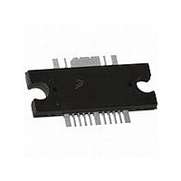
MW7IC2425NBR1 Freescale Semiconductor, MW7IC2425NBR1 Datasheet - Page 6

MW7IC2425NBR1
Manufacturer Part Number
MW7IC2425NBR1
Description
IC PWR AMP RF 2400MHZ TO-272-16
Manufacturer
Freescale Semiconductor
Datasheet
1.MW7IC2425GNR1.pdf
(21 pages)
Specifications of MW7IC2425NBR1
Current - Supply
195mA
Frequency
2.45GHz
Gain
27.7dB
Package / Case
TO-272-16
Rf Type
ISM
Test Frequency
2.45GHz
Voltage - Supply
28V
Channel Type
N
Channel Mode
Enhancement
Drain Source Voltage (max)
65V
Power Gain (typ)@vds
28.5dB
Frequency (max)
2.45GHz
Package Type
TO-272 WB EP
Pin Count
16
Output Capacitance (typ)@vds
111@28VpF
Operating Temp Range
-65C to 225C
Drain Efficiency (typ)
43.8%
Mounting
Surface Mount
Mode Of Operation
OFDM/WIMAX
Vswr (max)
10
Screening Level
Military
Lead Free Status / RoHS Status
Lead free / RoHS Compliant
Noise Figure
-
P1db
-
Lead Free Status / Rohs Status
Compliant
MW7IC2425NR1 MW7IC2425GNR1 MW7IC2425NBR1
6
30
29
28
27
26
25
Figure 5. Power Gain and Power Added Efficiency
1
P
versus CW Output Power
out
, OUTPUT POWER (WATTS) CW
V
I
I
f = 2450 MHz
DQ1
DQ2
DD
= 28 Vdc
= 55 mA
= 195 mA
10
30
29
28
27
26
25
30
29
28
27
26
25
TYPICAL CHARACTERISTICS — NARROWBAND
Figure 7. Power Gain and Power Added Efficiency
Figure 8. Power Gain and Power Added Efficiency
0.1
0.1
versus CW Output Power as a Function of V
versus CW Output Power as a Function of V
V
30 V
D1
30 V
= 32 V
28 V
32 V
V
D2
P
P
out
out
= 28 V
, OUTPUT POWER (WATTS) CW
, OUTPUT POWER (WATTS) CW
1
1
100
30
50
40
20
10
0
30 V
V
I
I
f = 2450 MHz
V
I
I
f = 2450 MHz
DQ1
DQ2
DQ1
DQ2
D2
D1
= 28 Vdc
= 28 Vdc
= 55 mA
= 195 mA
= 55 mA
= 195 mA
10
10
49
48
47
46
45
44
43
42
41
28 V
13
Figure 6. CW Output Power versus Input Power
P1dB = 44.5 dBm (28.05 W)
32 V
14
D1
D2
100
100
15
50
40
30
20
10
0
50
40
30
20
10
0
P
in
P3dB = 44.9 dBm (30.9 W)
, INPUT POWER (dBm)
16
V
I
DQ2
DD
Freescale Semiconductor
= 28 Vdc, I
= 195 mA, f = 2450 MHz
17
18
DQ1
RF Device Data
= 55 mA
Ideal
19
Actual
20


