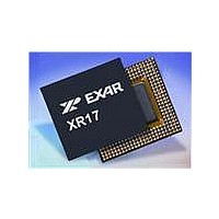
XR17V354IB176-F Exar Corporation, XR17V354IB176-F Datasheet - Page 58

XR17V354IB176-F
Manufacturer Part Number
XR17V354IB176-F
Description
IC UART PCIE 256B DUAL 176FPBGA
Manufacturer
Exar Corporation
Datasheet
1.XR17V354IB176-F.pdf
(66 pages)
Specifications of XR17V354IB176-F
Number Of Channels
4, QUART
Package / Case
176-LFBGA
Features
*
Fifo's
256 Byte
Protocol
RS485
Voltage - Supply
3.3V
With Auto Flow Control
Yes
With Irda Encoder/decoder
Yes
With False Start Bit Detection
Yes
With Modem Control
Yes
Mounting Type
Surface Mount
Data Rate
25 Mbps
Supply Current
120 mA
Maximum Operating Temperature
+ 85 C
Minimum Operating Temperature
- 40 C
Mounting Style
SMD/SMT
Operating Supply Voltage
3.3 V
No. Of Channels
4
Uart Features
Tx/Rx FIFO Counters
Supply Voltage Range
3V To 3.6V
Operating Temperature Range
-40°C To +85°C
Digital Ic Case Style
BGA
No. Of Pins
176
Rohs Compliant
Yes
Lead Free Status / RoHS Status
Lead free / RoHS Compliant
Lead Free Status / RoHS Status
Lead free / RoHS Compliant, Lead free / RoHS Compliant
Available stocks
Company
Part Number
Manufacturer
Quantity
Price
Company:
Part Number:
XR17V354IB176-F
Manufacturer:
EXAR
Quantity:
500
Company:
Part Number:
XR17V354IB176-F
Manufacturer:
Exar Corporation
Quantity:
10 000
Part Number:
XR17V354IB176-F
Manufacturer:
EXAR/艾科嘉
Quantity:
20 000
XR17V354
HIGH PERFORMANCE QUAD PCI-EXPRESS UART
MSR [2]: Receiver Disable
This bit can be used to disable the receiver by halting the Receive Shift Register (RSR). When this bit is set to
a logic 1, the receiver will operate in one of the following ways:
The receiver can be enabled and will start receiving characters by resetting this bit to a logic 0. The receiver
will operate in one of the following ways:
Any data that is in the RX FIFO can be read out at any time whether the receiver is disabled or not.
•
•
MSR [1]: Transmitter Disable Modes
This bit is only applicable when MSR[3] = 1.
•
•
MSR[0]: Receiver Disable Modes
This is only applicable when MSR[2] = 1.
•
•
This is a 8-bit general purpose register for the user to store temporary data. The content of this register is
preserved during sleep mode but becomes 0xFF (default) after a reset or a power off-on cycle.
This register controls the UART enhanced functions that are not available on ST16C554 or ST16C654.
FCTR[7:6]: TX and RX FIFO Trigger Table Select
These 2 bits select the transmit and receive FIFO trigger level table A, B, C or D. When table A, B, or C is
selected the auto RTS flow control trigger level is set to "next FIFO trigger level" for compatibility to ST16C550
and ST16C650 series. RTS/DTR# triggers on the next level of the RX FIFO trigger level, in another word, one
FIFO level above and one FIFO level below. See in
FCTR bits [7:6], i.e. if Table C is used on the receiver with RX FIFO trigger level set to 56 bytes, RTS/DTR#
output will de-assert at 60 and re-assert at 16.
4.12
4.13
Logic 0 = Enable Receiver (default).
Logic 1 = Disable Receiver.
Logic 0 = No xon/xoff software flow control characters will be transmitted when the transmitter is disabled. If
there is a pending xon/xoff character to be sent while the transmitter is disabled, it will be transmitted. No
additional xon/xoff characters will be sent.
Logic 1 = Xon/xoff software flow control characters will be transmitted even though the transmitter is
disabled.
Logic 0 = All RX data and xon/xoff flow control characters are ignored.
Logic 1 = All RX data is ignored. Xon/xoff flow control characters are detected and acted upon.
■
■
■
■
If a character is being received at the time of setting this bit, that character will be correctly received. No
more characters will be received.
If the receiver is idle at the time of setting this bit, no more characters will be received.
If the receiver is idle (RX pin is HIGH) at the time of setting this bit, the next character will be received
normally. It is recommended that the receiver be idle when resetting this bit to a logic 0.
If the receiver is not idle (RX pin is toggling) at the time of setting this bit, the RX FIFO will be filled with
unknown data.
SCRATCH PAD REGISTER (SPR) - Read/Write
FEATURE CONTROL REGISTER (FCTR) - Read/Write
58
Table 16
for complete selection with FCR bit [5:4] and
REV. 1.0.1


