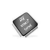
STM32100B-EVAL STMicroelectronics, STM32100B-EVAL Datasheet - Page 11

STM32100B-EVAL
Manufacturer Part Number
STM32100B-EVAL
Description
MCU, MPU & DSP Development Tools STM32 ARM Value Line Eval Board
Manufacturer
STMicroelectronics
Specifications of STM32100B-EVAL
Processor To Be Evaluated
STM32F100VB
Data Bus Width
32 bit
Interface Type
RS-232, USB, I2C, SPI, USART
Operating Supply Voltage
3.3 V
Silicon Manufacturer
ST Micro
Core Architecture
ARM
Core Sub-architecture
Cortex - M3
Silicon Core Number
STM32
Silicon Family Name
STM32F1xx
Kit Contents
Board
Features
IrDA Transceiver,
Lead Free Status / RoHS Status
Lead free / RoHS Compliant
UM0841
2.12
2.13
2.14
Analog input
One BNC connector, CN7, is connected to PA4 of the STM32F100VBT6 microcontroller as
an external analog input. or DAC output. The 50Ω terminal resistor can be enabled by
closing solder bridge SB1. A low pass filter can be implemented for the BNC connector by
replacing R44 and C33 for ADC input, or replacing R43 and C33 for DAC output with the
correct value of resistor and capacitor as requested by the end user's application.
There are also 3 analog signals available on the board:
1.
2.
3.
IrDA
IrDA communication is supported by the IrDA transceiver U14, which is connected to
USART3 of the STM32F100VBT6 microcontroller. It is enabled or disabled by jumper JP11.
Table 7.
Display and input devices
The 240x320 TFT color LCD (mounted on connector CN14) and 4 general purpose LEDs
(LD1, 2, 3, 4) are available as display devices.
A 4-direction joystick with selection key, general purpose push button (B4), wakeup button
(B2) and tamper detection button (B3) are available as input devices.
Table 8.
Jumper
CN14 pin
JP11
10 KΩ potentiometer RV2 connected to PC4.
IDD measurement output signal connected to PC5 for MCU power consumption test.
External ADC input which can be connected to TP3 (AIN+) and TP2 (AIN-), R45 should
be removed to avoid noise.
1
2
3
4
5
6
7
8
Enables/disables the IrDA transceiver. IrDA is enabled when JP11 is fitted, and disabled
when JP11 is not fitted.
Default setting: Fitted
IrDA jumper
240x320 TFT color LCD modules
CS
SCL
SDI
RS
WR
RD
SDO
RESET#
Description
PB2
PB13
PB15
PB14
RESET#
Pin connection
Doc ID 16533 Rev 2
Description
CN14 pin
11
12
13
14
15
16
10
9
Hardware layout and configuration
VDD
VCI
GND
GND
BL_VDD
BL_Control
BL_GND
BL_GND
Description
+3V3
+3V3
GND
GND
+3V3
PA8
GND
GND
Pin connection
11/41


