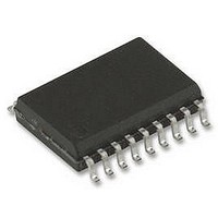
ST62T15CM6 STMicroelectronics, ST62T15CM6 Datasheet - Page 22

ST62T15CM6
Manufacturer Part Number
ST62T15CM6
Description
8BIT MCU OTP 2K, SMD, 62T15, SOIC20
Manufacturer
STMicroelectronics
Datasheet
1.ST62T15CB6.pdf
(105 pages)
Specifications of ST62T15CM6
Controller Family/series
ST6
Core Size
8bit
No. Of I/o's
20
Program Memory Size
2KB
Ram Memory Size
64Byte
Cpu Speed
8MHz
Oscillator Type
External Only
No. Of Timers
1
Digital Ic Case
RoHS Compliant
Peripherals
ADC,
Rohs Compliant
No
Processor Series
ST62T1x
Core
ST6
Data Bus Width
8 bit
Program Memory Type
EPROM
Data Ram Size
64 B
Maximum Clock Frequency
8 MHz
Number Of Programmable I/os
20
Number Of Timers
2
Operating Supply Voltage
3 V to 6 V
Maximum Operating Temperature
+ 85 C
Mounting Style
SMD/SMT
Package / Case
SOP-28
Development Tools By Supplier
ST62GP-EMU2, ST62E2XC-EPB/110, ST62E6XC-EPB/US, STREALIZER-II
Minimum Operating Temperature
- 40 C
On-chip Adc
8 bit
Lead Free Status / Rohs Status
In Transition
Available stocks
Company
Part Number
Manufacturer
Quantity
Price
Company:
Part Number:
ST62T15CM6
Manufacturer:
STM
Quantity:
2 508
Part Number:
ST62T15CM6
Manufacturer:
ST
Quantity:
20 000
ST6215C/ST6225C
CLOCK SYSTEM (Cont’d)
5.1.3 Low Frequency Auxiliary Oscillator
The Low Frequency Auxiliary Oscillator has three
main purposes. Firstly, it can be used to reduce
power consumption in non timing critical routines.
Secondly, it offers a fully integrated system clock,
without any external components. Lastly, it acts as
a backup oscillator in case of main oscillator fail-
ure.
This oscillator is available when the OSG ENA-
BLED option is selected in the option byte (refer to
the Option Bytes section of this document). In this
case, it automatically starts one of its periods after
the first missing edge of the main oscillator, what-
ever the reason for the failure (main oscillator de-
fective, no clock circuitry provided, main oscillator
switched off...). See
User code, normal interrupts, WAIT and STOP in-
structions, are processed as normal, at the re-
duced f
cy is decreased, since the internal frequency is be-
low 1.2 MHz.
At power on, until the main oscillator starts, the re-
set delay counter is driven by the LFAO. If the
main oscillator starts before the 2048 cycle delay
has elapsed, it takes over.
22/105
1
(LFAO)
LFAO
frequency. The A/D converter accura-
Figure
11.
The Low Frequency Auxiliary Oscillator is auto-
matically switched off as soon as the main oscilla-
tor starts.
5.1.4 Register Description
ADC CONTROL REGISTER (ADCR)
Address: 0D1h — Read/Write
Reset value: 0100 0000 (40h)
Bit 7:3, 1:0 = ADCR[7:3], ADCR[1:0] ADC Control
Register .
These bits are used to control the A/D converter (if
available on the device) otherwise they are not
used.
Bit 2 = OSCOFF Main Oscillator Off.
0: Main oscillator enabled
1: Main oscillator disabled
Note: The OSG must be enabled using the OS-
GEN option in the Option Byte, otherwise the OS-
COFF setting has no effect.
ADCR
7
7
ADCR
6
ADCR
5
ADCR
4
ADCR
3
OSC
OFF
ADCR
1
ADCR
0
0


