H3DS-AL Omron, H3DS-AL Datasheet - Page 12
H3DS-AL
Manufacturer Part Number
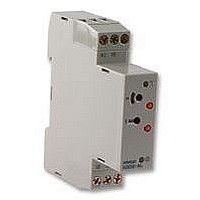
H3DS-AL
Description
Multifunction Timer
Manufacturer
Omron
Datasheet
1.H3DS-ML.pdf
(13 pages)
Specifications of H3DS-AL
Time Range
0.1 To 1.2 Sec, 10 - 120 Hr
Supply Voltage Ac, Min
24VAC
Supply Voltage Dc, Max
48VDC
Supply Voltage Dc, Min
24VDC
Length/height, External
80mm
Supply Voltage Ac, Max
230VAC
External Width
17.5mm
External Depth
73mm
Operating Temperature Max
55°C
Operating Temperature Min
-10°C


H3DS
Precautions
NOTICE:
The H3DS Series is provided with a transformerless power supply
system. An electric shock may be received if the input terminal or
the output type selector switch is touched while power is being sup-
plied.
Use the bar terminal for wiring the H3DS. Using a stranded-wire ter-
minal may cause a short-circuit due to a stray wire entering into the
Timer.
Both AC and DC power supplies can be connected to the power in-
put terminals without regarding polarity.
With the H3DS only, a DC power supply must be connected to the
power input terminals as designated according to the polarity of the
terminals.
A DC power supply can be connected if its ripple factor is 20% or
less and the mean voltage is within the rated operating voltage
range of the Timer.
Make sure that the voltage is applied within the specified range,
otherwise the internal elements of the Timer may be damaged.
Connect the power supply voltage through a relay or switch in such
a way that the voltage reaches a fixed value at once or the Timer
may not be reset or a timer error could result.
For the power supply of an input device of the H3DS-MLj, use an
isolating transformer, of which the primary and secondary windings
are mutually isolated and the secondary winding is not grounded.
If the load current is continuously being supplied to the Timer for a
long period of time, be sure to provide the mounting clearance as
shown in the figure below. If used under the conditions other than
those specified below, the life of internal components may be short-
ened due to an excessive rise in the internal temperature.
Changing of Setting
Power Supplies
Installation
Do not change the time scale or operating mode, while
the Timer is in operation or malfunction could result.
H3DS
Circuit
Start
input
B1
t
H3DS-MLj
H3DS
t: Mounting clearance (mm)
A1
A2
Isolation transformer is required.
t
H3DS
Power supply
DIN track
Switching Current vs. Ambient Temperature
(When Mounting Two or More H3DS Units Side-by-Side)
Relationship between Input and Power Supply
Circuits (H3DS-MLj)
Since the input circuit and the power supply circuit are configured
independently, the input circuit can be turned on or off irrespective of
the on/off state of the power supply.
It must be noted that a voltage equivalent to the power supply volt-
age is applied to the input circuit.
When connecting a relay or a transistor as an external signal input
device, pay attention to the following points to prevent short-circuit-
ing due to a sneak current to the transformerless power supply.
If a relay or transistor is connected to two or more Timers, the input
terminals of those Timers must be wired properly so that they will not
be different in phase or the terminals will be short-circuited to one
another (refer to the figures below).
(Measurement Condition: Input voltage of 230 VAC)
Incorrect
Input/Output
70
60
50
40
30
Contact or transistor for
external input signal
Short-circuit
current
0
AC/DC
power
supply
1
2
B1
B1
Input circuit
3
H3DS-MLj
H3DS-MLj
B1
4
A1
A2
A1
A2
A2
Power supply
circuit
5
Mounting
clearance: 5 mm
Mounting clearance:
50 mm min.
Mounting
clearance: 10 mm
Mounting
clearance: 0 mm
A1
Load current (A)
Maximum range of
operating ambient
temperature
Power supply
H3DS
15
Related parts for H3DS-AL
Image
Part Number
Description
Manufacturer
Datasheet
Request
R

Part Number:
Description:
TIMER, 8 MODE
Manufacturer:
Omron
Datasheet:

Part Number:
Description:
TIMER CAGE CLAMP 17.5MM 4MODES
Manufacturer:
Omron
Datasheet:
Part Number:
Description:
TIMER CAGE CLAMP 17.5MM 8MODES
Manufacturer:
Omron
Datasheet:

Part Number:
Description:
RELAY TIME DELAY 1MODE DIN MNT
Manufacturer:
Omron
Datasheet:

Part Number:
Description:
RELAY TIME DELAY 8MODE DIN MNT
Manufacturer:
Omron
Datasheet:

Part Number:
Description:
17.5mm TWIN TIMER
Manufacturer:
Omron
Datasheet:

Part Number:
Description:
17.5mm TIMER DIN. MNT.
Manufacturer:
Omron
Datasheet:
Part Number:
Description:
TIMER, 4 MODE
Manufacturer:
Omron
Datasheet:

Part Number:
Description:
Solid-state Timer
Manufacturer:
Omron Corporation
Datasheet:

Part Number:
Description:
LOCK KEY PEN FOR H3DS RELAYS
Manufacturer:
Omron
Datasheet:
Part Number:
Description:
G6S-2GLow Signal Relay
Manufacturer:
Omron Corporation
Datasheet:
Part Number:
Description:
Compact, Low-cost, SSR Switching 5 to 20 A
Manufacturer:
Omron Corporation
Datasheet:
Part Number:
Description:
Manufacturer:
Omron Corporation
Datasheet: