GRM21BR71H104KA01L Murata, GRM21BR71H104KA01L Datasheet - Page 175
GRM21BR71H104KA01L
Manufacturer Part Number
GRM21BR71H104KA01L
Description
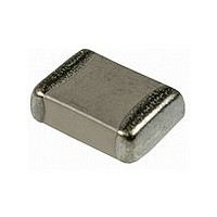
CAPACITOR, 0805 100NF 50V CAPACITOR, 0805 100NF 50V
Manufacturer
Murata
Series
GRM21r
Specifications of GRM21BR71H104KA01L
Tolerance (+ Or -)
10%
Voltage
50VDC
Temp Coeff (dielectric)
X7R
Operating Temp Range
-55C to 125C
Mounting Style
Surface Mount
Construction
SMT Chip
Case Style
Ceramic Chip
Failure Rate
Not Required
Wire Form
Not Required
Product Length (mm)
2mm
Product Depth (mm)
1.25mm
Product Height (mm)
1.25mm
Product Diameter (mm)
Not Requiredmm
Capacitance
.1uF
Package / Case
0805
Voltage Rating, Dc
50V
Capacitor Dielectric Type
CERAMIC MULTI-LAYER
Tolerance,
10%
Tolerance, -
10%
Temp, Op. Max
125(DEGREE C)
Temp,
ROHS COMPLIANT
Lead Free Status / RoHS Status
Compliant
Available stocks
Company
Part Number
Manufacturer
Quantity
Price
Company:

Part Number:
GRM21BR71H104KA01L
Manufacturer:
MURATA
Quantity:
640 000
Company:
Part Number:
GRM21BR71H104KA01L
Manufacturer:
MURATA
Quantity:
400 000
Company:
Part Number:
GRM21BR71H104KA01L
Manufacturer:
MURATA
Quantity:
189 000
Part Number:
GRM21BR71H104KA01L 0805 X7R 104K 50V
Manufacturer:
MURATA/村田
Quantity:
20 000


!Note
• This PDF catalog is downloaded from the website of Murata Manufacturing co., ltd. Therefore, it’s specifications are subject to change or our products in it may be discontinued without advance notice. Please check with our
• This PDF catalog has only typical specifications because there is no space for detailed specifications. Therefore, please approve our product specifications or transact the approval sheet for product specifications before ordering.
sales representatives or product engineers before ordering.
!Note
174
No.
11 Deflection
12
13
14
15
* "Room condition" Temperature: 15 to 35 C, Relative humidity: 45 to 75%, Atmospheric pressure: 86 to 106kPa
Medium Voltage Soft Termination Type GRJ Series Specifications and Test Methods
GRJ Series Specifications and Test Methods
Continued from the preceding page.
Solderability of
Termination
Resistance
to Soldering
Heat
Temperature
Cycle
Humidity
(Steady
State)
• Please read rating and !CAUTION (for storage, operating, rating, soldering, mounting and handling) in this catalog to prevent smoking and/or burning, etc.
• This catalog has only typical specifications because there is no space for detailed specifications. Therefore, please approve our product specifications or transact the approval sheet for product specifications before ordering.
Item
Appearance
Capacitance
Change
Appearance No marking defects
Capacitance
Change
D.F.
I.R.
Dielectric
Strength
Appearance No marking defects
Capacitance
Change
D.F.
I.R.
Dielectric
Strength
Appearance No marking defects
Capacitance
Change
D.F.
I.R.
Dielectric
Strength
No marking defects
Within 12.5%
75% of the terminations are to be soldered evenly and continuously.
Within 10%
0.025 max.
CU0.01 F: More than 100M • F
CF0.01 F: More than 10,000M
In accordance with item No.4
Within 7.5%
0.025 max.
CU0.01 F: More than 100M • F
CF0.01 F: More than 10,000M
In accordance with item No.4
Within 15%
0.05 max.
CU0.01 F: More than 10M • F
CF0.01 F: More than 1,000M
In accordance with item No.4
2.0Z1.25
3.2Z1.6
3.2Z2.5
4.5Z3.2
5.7Z5.0
LZW
(mm)
1.2
2.2
2.2
3.5
4.5
a
Specifications
d
100
b
a
Fig. 2
c
Dimension (mm)
4.0
5.0
5.0
7.0
8.0
b
4.5
t : 1.6
1.65
2.0
2.9
3.7
5.6
c
1.0
d
Solder the capacitor to the testing jig (glass epoxy board) shown
in Fig. 2.
Then apply a force in the direction shown in Fig. 3.
The soldering should be done using the reflow method and
should be conducted with care so that the soldering is uniform
and free of defects such as heat shock.
Immerse the capacitor in a solution of ethanol (JIS-K-8101) and
rosin (JIS-K-5902) (25% rosin in weight proportion).
Immerse in solder solution for 2 0.5 sec.
Immersing speed: 25 2.5mm/s
Temp. of solder: 245 5 C Lead Free Solder (Sn-3.0Ag-0.5Cu)
Preheat the capacitor at 120 to 150 C * for 1 min.
Immerse the capacitor in solder solution at 260 5 C for 10 1
sec. Let sit at room condition* for 24 2 hrs., then measure.
*Preheating for more than 3.2Z2.5mm
Fix the capacitor to the supporting jig (glass epoxy board) shown
in Fig. 4.
Perform the 5 cycles according to the 4 heat treatments listed in
the following table.
Let sit for 24 2 hrs. at room condition,* then measure.
Let the capacitor sit at 40 2 C and relative humidity of 90 to 95%
for 500
Remove and let sit for 24 2 hrs. at room condition,* then
measure.
•Immersing speed: 25 2.5mm/s
•Pretreatment
•Pretreatment
•Pretreatment
Perform a heat treatment at 150
let sit for 24 2 hrs. at room condition.*
Perform a heat treatment at 150
let sit for 24 2 hrs. at room condition.*
Perform a heat treatment at 150
let sit for 24 2 hrs. at room condition.*
Step
Step
+24
1
2
1
2
3
4
– 0
hrs.
Max. Operating Temp. 2
Min. Operating Temp. 3
235 5 C H60A or H63A Eutectic Solder
Temperature ( C)
Glass Epoxy Board
Temperature
R230
100 to 120 C
170 to 200 C
Room Temp.
Room Temp.
Capacitance meter
45
Test Method
20 50
Fig. 3
Fig. 4
Continued on the following page.
45
Pressurize
+ 0
+ 0
+ 0
–10
–10
–10
Pressurizing
speed: 1.0mm/s
Flexure=3
C for 60 5 min. and then
C for 60 5 min. and then
C for 60 5 min. and then
Solder resist
Cu
(in mm)
Time (min.)
1 min.
1 min.
2 to 3
2 to 3
Time
30 3
30 3
C02E.pdf
10.12.20
Related parts for GRM21BR71H104KA01L
Image
Part Number
Description
Manufacturer
Datasheet
Request
R

Part Number:
Description:
Murata Microblower 20x20 DCDC Driver Board - Samples Only
Manufacturer:
Murata
Part Number:
Description:
357-036-542-201 CARDEDGE 36POS DL .156 BLK LOPRO
Manufacturer:
Murata
Datasheet:
Part Number:
Description:
Manufacturer:
Murata
Datasheet:
Part Number:
Description:
Manufacturer:
Murata
Datasheet:
Part Number:
Description:
Manufacturer:
Murata
Datasheet:
Part Number:
Description:
Manufacturer:
Murata
Datasheet:
Part Number:
Description:
Manufacturer:
Murata
Datasheet:
Part Number:
Description:
Manufacturer:
Murata
Datasheet:
Part Number:
Description:
Manufacturer:
Murata
Datasheet:
Part Number:
Description:
BLM21BD751SN1On-Board Type (DC) EMI Suppression Filters
Manufacturer:
Murata
Datasheet:
Part Number:
Description:
BLM15AG100SN1On-Board Type (DC) EMI Suppression Filters
Manufacturer:
Murata
Datasheet:
Part Number:
Description:
NFE31PT222Z1E9On-Board Type (DC) EMI Suppression Filters
Manufacturer:
Murata
Datasheet:
Part Number:
Description:
Chip Coil
Manufacturer:
Murata
Datasheet:
Part Number:
Description:
Chip Coil
Manufacturer:
Murata
Datasheet: