CSTCR4M00G53Z-R0 Murata Electronics North America, CSTCR4M00G53Z-R0 Datasheet - Page 10
CSTCR4M00G53Z-R0
Manufacturer Part Number
CSTCR4M00G53Z-R0
Description
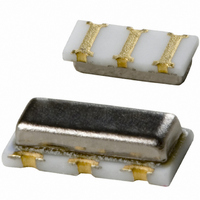
RESONATOR 4.00MHZ CERAMIC INDUST
Manufacturer
Murata Electronics North America
Series
CERALOCK®, CSTCRr
Type
Ceramicr
Specifications of CSTCR4M00G53Z-R0
Frequency
4MHz
Features
Built in Capacitor
Frequency Stability
±0.2%
Frequency Tolerance
±0.5%
Impedance
60 Ohm
Capacitance
15pF
Operating Temperature
-40°C ~ 125°C
Mounting Type
Surface Mount
Package / Case
3-SMD, Non-Standard
Size / Dimension
0.177" L x 0.079" W (4.50mm x 2.00mm)
Height
0.045" (1.15mm)
Lead Free Status / RoHS Status
Lead free / RoHS Compliant
Other names
490-1217-2
Available stocks
Company
Part Number
Manufacturer
Quantity
Price
Company:

Part Number:
CSTCR4M00G53Z-R0
Manufacturer:
MURATA
Quantity:
240 000


2
Note
• This PDF catalog is downloaded from the website of Murata Manufacturing co., ltd. Therefore, it’s specifications are subject to change or our products in it may be discontinued without advance notice. Please check with our
• This PDF catalog has only typical specifications because there is no space for detailed specifications. Therefore, please approve our product specifications or transact the approval sheet for product specifications before ordering.
sales representatives or product engineers before ordering.
Fig. 2-1 shows the symbol for a ceramic resonator. The
impedance and phase characteristics measured between
the terminals are shown in Fig. 2-2. This illustrates that
the resonator becomes inductive in the frequency zone
between the frequency Fr (resonant frequency), which
provides the minimum impedance, and the frequency Fa
(anti-resonant frequency), which provides the maximum
impedance.
It becomes capacitive in other frequency zones. This
means that the mechanical vibration of a two terminal
resonator can be replaced equivalently with a
combination of series and parallel resonant circuits
consisting of an inductor : L, a capacitor : C, and a
resistor : R. In the vicinity of the specific frequency
(Refer to Note 1 on page 10.), the equivalent circuit can
be expressed as shown in Fig. 2-3.
Fr and Fa frequencies are determined by the
piezoelectric ceramic material and the physical
parameters. The equivalent circuit constants can be
determined from the following formulas. (Refer to Note
2 on page 10.)
Fr=1/2�
Fa=1/2�
Considering the limited frequency range of Fr≦F≦Fa,
the impedance is given as Z=Re+j ω Le (Le≧0) as shown
in Fig. 2-4, and CERALOCK
inductance Le (H) having the loss Re (Ω).
8
Qm=1/2�FrC
(Qm : Mechanical Q)
1. Equivalent Circuit Constants
2
L
L
Principles of CERALOCK
1
1
C
C
1
1
R
1
C
1
0
/(C
1
+C
0
)=Fr 1+C
®
should work as an
1
/C
0
(2-1)
(2-2)
(2-3)
Fig. 2-2 Impedance and Phase Characteristics of CERALOCK
Fig. 2-3 Electrical Equivalent Circuit of CERALOCK
Fig. 2-1 Symbol of the Two Terminal CERALOCK
Fig. 2-4 Equivalent Circuit of CERALOCK
Symbol
10
10
10
10
-90
10
90
R
L
C
C
0
5
4
3
2
in the Frequency Band Fr
1
1
1
0
: Equivalent Inductance
: Equivalent Resistance
: Equivalent Capacitance
: Parallel Equivalent Capacitance
Impedance between Two Terminals Z=R+jx
(R : Real Component, X : Impedance Component)
Phase φ =tan
Re
Re : Effective Resistance
Le : Effective Inductance
L
1
Fr
®
C
C
1
0
-1
X/R
Fa
R
Le
1
Frequency (kHz)
≦
F
≦
Fa
®
®
®
P17E.pdf
®
10.8.3
Related parts for CSTCR4M00G53Z-R0
Image
Part Number
Description
Manufacturer
Datasheet
Request
R

Part Number:
Description:
BUZZER PIEZO 25VP-P SMD
Manufacturer:
Murata Electronics North America

Part Number:
Description:
CAP 4-ARRAY 680PF 100V X7R 1206
Manufacturer:
Murata Electronics North America
Datasheet:
Part Number:
Description:
CAP 4-ARRAY 1000PF 100V X7R 1206
Manufacturer:
Murata Electronics North America
Datasheet:
Part Number:
Description:
CAP 4-ARRAY 1800PF 100V X7R 1206
Manufacturer:
Murata Electronics North America
Datasheet:
Part Number:
Description:
CAP 4-ARRAY 68000PF 16V X7R 1206
Manufacturer:
Murata Electronics North America
Datasheet:

Part Number:
Description:
CAP CER 1000PF 50V 10% X7R 0402
Manufacturer:
Murata Electronics North America
Datasheet:
Part Number:
Description:
CAP CER 10000PF 16V 10% X7R 0402
Manufacturer:
Murata Electronics North America
Datasheet:

Part Number:
Description:
CAP 5.5-25PF 2.5X3.2MM SMD
Manufacturer:
Murata Electronics North America
Datasheet:

Part Number:
Description:
CAP 4.5-20PF 2.5X3.2MM SMD
Manufacturer:
Murata Electronics North America
Datasheet:

Part Number:
Description:
CAP 5.0-20PF 3.2X4.5MM SMD RED
Manufacturer:
Murata Electronics North America
Datasheet:

Part Number:
Description:
CAP 2.0-6.0PF 3.2X4.5MM SMD BLU
Manufacturer:
Murata Electronics North America
Datasheet:

Part Number:
Description:
CAP 1.4-3.0PF 3.2X4.5MM SMD BRN
Manufacturer:
Murata Electronics North America
Datasheet:

Part Number:
Description:
CAP 3.0-10PF 3.2X4.5MM SMD WHT
Manufacturer:
Murata Electronics North America
Datasheet:

Part Number:
Description:
CAP 2.0-6.0PF 4X4.5MM TOPADJ BLU
Manufacturer:
Murata Electronics North America
Datasheet:

Part Number:
Description:
CAP 8.5-40PF 4X4.5MM TOPADJ YEL
Manufacturer:
Murata Electronics North America
Datasheet: