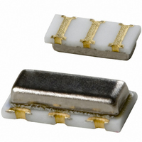
CSTCR4M00G53Z-R0 Murata Electronics North America, CSTCR4M00G53Z-R0 Datasheet - Page 12

CSTCR4M00G53Z-R0
Manufacturer Part Number
CSTCR4M00G53Z-R0
Description
RESONATOR 4.00MHZ CERAMIC INDUST
Manufacturer
Murata Electronics North America
Series
CERALOCK®, CSTCRr
Type
Ceramicr
Specifications of CSTCR4M00G53Z-R0
Frequency
4MHz
Features
Built in Capacitor
Frequency Stability
±0.2%
Frequency Tolerance
±0.5%
Impedance
60 Ohm
Capacitance
15pF
Operating Temperature
-40°C ~ 125°C
Mounting Type
Surface Mount
Package / Case
3-SMD, Non-Standard
Size / Dimension
0.177" L x 0.079" W (4.50mm x 2.00mm)
Height
0.045" (1.15mm)
Lead Free Status / RoHS Status
Lead free / RoHS Compliant
Other names
490-1217-2
Available stocks
Company
Part Number
Manufacturer
Quantity
Price
Company:
Part Number:
CSTCR4M00G53Z-R0
Manufacturer:
MURATA
Quantity:
240 000
2
Note
• This PDF catalog is downloaded from the website of Murata Manufacturing co., ltd. Therefore, it’s specifications are subject to change or our products in it may be discontinued without advance notice. Please check with our
• This PDF catalog has only typical specifications because there is no space for detailed specifications. Therefore, please approve our product specifications or transact the approval sheet for product specifications before ordering.
sales representatives or product engineers before ordering.
10
2
(Note 1)
The relationship between the size of the resonator
and the resonant frequency is described as follows.
For example, the frequency doubles if the thickness
doubles, when thickness vibration is used.
The following relationship is obtained when the
length of the resonators is ℓ, the resonance
frequency is Fr, the speed of sound waves travelling
through piezoelectric ceramics, and the wavelength
is λ.
As seen in the above formula, the frequency
constant determines the size of the resonator.
Principles of CERALOCK
Notes
Fr . ℓ = Const.
(frequency constant, Fr . t for the thickness)
λ = 2 ℓ
C = Fr . λ = 2Fr . ℓ
(Min.Amplitude) (Max.Amplitude)
Fig. Ⅰ
Amplitude
Range of
Standing
Wave
®
(Note 2)
In Fig. 2-3, when resistance R
simplification, the impedance Z (ω) between two
terminals is expressed by the following formula.
Therefore from ω =2�F,
Fr = ωr/2� =
Fa = ωa/2� =
Z (ω) =
When ω =
When ω =
=
j ( ωL
1 +
jωC
jωC
1
1
2�
2�
0
0
C
L
C
C
1
1 –
1
( jωL
+ ( jωL
0
0
1
C
C
1
L
1
1
ωC
C
L
– ω
1
0
1
= ωr, Z (ωr) =0
C
L
1
1
C
1
1
Fig. Ⅱ
/(C
1
+
1
1
2
1
1
L
C
jωC
+
)
C
0+
0
1
1
/(C
jωC
0
C
L
C
1
1
1
1
1
)
0
1
+C
)
1
is omitted for
= ωa, Z (ωa) = ∞
)
1
)
= Fr
1+
C
C
1
0
P17E.pdf
10.8.3


