CSTCR4M00G53Z-R0 Murata Electronics North America, CSTCR4M00G53Z-R0 Datasheet - Page 20
CSTCR4M00G53Z-R0
Manufacturer Part Number
CSTCR4M00G53Z-R0
Description
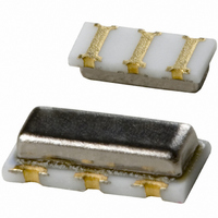
RESONATOR 4.00MHZ CERAMIC INDUST
Manufacturer
Murata Electronics North America
Series
CERALOCK®, CSTCRr
Type
Ceramicr
Specifications of CSTCR4M00G53Z-R0
Frequency
4MHz
Features
Built in Capacitor
Frequency Stability
±0.2%
Frequency Tolerance
±0.5%
Impedance
60 Ohm
Capacitance
15pF
Operating Temperature
-40°C ~ 125°C
Mounting Type
Surface Mount
Package / Case
3-SMD, Non-Standard
Size / Dimension
0.177" L x 0.079" W (4.50mm x 2.00mm)
Height
0.045" (1.15mm)
Lead Free Status / RoHS Status
Lead free / RoHS Compliant
Other names
490-1217-2
Available stocks
Company
Part Number
Manufacturer
Quantity
Price
Company:

Part Number:
CSTCR4M00G53Z-R0
Manufacturer:
MURATA
Quantity:
240 000


3
Note
• This PDF catalog is downloaded from the website of Murata Manufacturing co., ltd. Therefore, it’s specifications are subject to change or our products in it may be discontinued without advance notice. Please check with our
• This PDF catalog has only typical specifications because there is no space for detailed specifications. Therefore, please approve our product specifications or transact the approval sheet for product specifications before ordering.
sales representatives or product engineers before ordering.
∗ CSTCC Series : within±0.3%
18
■
Type
Every Series
3
Deviation after Reliability Test
fosc. 0
fosc. 0
-0.05
-0.05
0.05
0.05
(%)
(%)
-0.1
-0.1
0.1
0.1
Specifications of CERALOCK
1. Shock Resistance
5. Storage at High Temperature
before test
100
Fig. 3-2 General Changes of Oscillation Frequency in Each Reliability Test (CSTLS4M00G53–B0)
Item
1000
after test
Oscillation Frequency
(from initial value)
(time)
within±0.2%
fosc. 0
fosc. 0
-0.05
-0.05
*
0.05
0.05
(%)
(%)
-0.1
-0.1
0.1
0.1
2. Solder Heat Resistance
6. Storage at Low Temperature
before test
Meets the individual
specification of each
product.
100
Others
®
1000
after test
(time)
fosc. 0
fosc. 0
-0.05
-0.05
(%)
0.05
(%)
0.05
-0.1
-0.1
0.1
0.1
before test
3. Vibration Resistance
7. Temperature Cycling
Fig. 3-3 Reflow Soldering Profile for MHz Band Chip
25
220
150
260
245
180
CERALOCK
50
after test
(cycle)
(150 to 180°C)
100
Pre-heating
60 to 120s
®
fosc. 0
fosc. 0
-0.05
-0.05
0.05
0.05
(%)
(%)
-0.1
-0.1
0.1
0.1
4. Humidity Resistance
8. Terminal Strength
before test
(220°C min.)
30 to 60s
Heating
100
Peak
Gradual
Cooling
1000
after test
(time)
P17E.pdf
10.8.3
Related parts for CSTCR4M00G53Z-R0
Image
Part Number
Description
Manufacturer
Datasheet
Request
R

Part Number:
Description:
BUZZER PIEZO 25VP-P SMD
Manufacturer:
Murata Electronics North America

Part Number:
Description:
CAP 4-ARRAY 680PF 100V X7R 1206
Manufacturer:
Murata Electronics North America
Datasheet:
Part Number:
Description:
CAP 4-ARRAY 1000PF 100V X7R 1206
Manufacturer:
Murata Electronics North America
Datasheet:
Part Number:
Description:
CAP 4-ARRAY 1800PF 100V X7R 1206
Manufacturer:
Murata Electronics North America
Datasheet:
Part Number:
Description:
CAP 4-ARRAY 68000PF 16V X7R 1206
Manufacturer:
Murata Electronics North America
Datasheet:

Part Number:
Description:
CAP CER 1000PF 50V 10% X7R 0402
Manufacturer:
Murata Electronics North America
Datasheet:
Part Number:
Description:
CAP CER 10000PF 16V 10% X7R 0402
Manufacturer:
Murata Electronics North America
Datasheet:

Part Number:
Description:
CAP 5.5-25PF 2.5X3.2MM SMD
Manufacturer:
Murata Electronics North America
Datasheet:

Part Number:
Description:
CAP 4.5-20PF 2.5X3.2MM SMD
Manufacturer:
Murata Electronics North America
Datasheet:

Part Number:
Description:
CAP 5.0-20PF 3.2X4.5MM SMD RED
Manufacturer:
Murata Electronics North America
Datasheet:

Part Number:
Description:
CAP 2.0-6.0PF 3.2X4.5MM SMD BLU
Manufacturer:
Murata Electronics North America
Datasheet:

Part Number:
Description:
CAP 1.4-3.0PF 3.2X4.5MM SMD BRN
Manufacturer:
Murata Electronics North America
Datasheet:

Part Number:
Description:
CAP 3.0-10PF 3.2X4.5MM SMD WHT
Manufacturer:
Murata Electronics North America
Datasheet:

Part Number:
Description:
CAP 2.0-6.0PF 4X4.5MM TOPADJ BLU
Manufacturer:
Murata Electronics North America
Datasheet:

Part Number:
Description:
CAP 8.5-40PF 4X4.5MM TOPADJ YEL
Manufacturer:
Murata Electronics North America
Datasheet: