CSTCR4M00G53Z-R0 Murata Electronics North America, CSTCR4M00G53Z-R0 Datasheet - Page 19
CSTCR4M00G53Z-R0
Manufacturer Part Number
CSTCR4M00G53Z-R0
Description
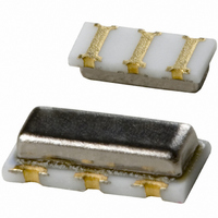
RESONATOR 4.00MHZ CERAMIC INDUST
Manufacturer
Murata Electronics North America
Series
CERALOCK®, CSTCRr
Type
Ceramicr
Specifications of CSTCR4M00G53Z-R0
Frequency
4MHz
Features
Built in Capacitor
Frequency Stability
±0.2%
Frequency Tolerance
±0.5%
Impedance
60 Ohm
Capacitance
15pF
Operating Temperature
-40°C ~ 125°C
Mounting Type
Surface Mount
Package / Case
3-SMD, Non-Standard
Size / Dimension
0.177" L x 0.079" W (4.50mm x 2.00mm)
Height
0.045" (1.15mm)
Lead Free Status / RoHS Status
Lead free / RoHS Compliant
Other names
490-1217-2
Available stocks
Company
Part Number
Manufacturer
Quantity
Price
Company:

Part Number:
CSTCR4M00G53Z-R0
Manufacturer:
MURATA
Quantity:
240 000


Note
• This PDF catalog is downloaded from the website of Murata Manufacturing co., ltd. Therefore, it’s specifications are subject to change or our products in it may be discontinued without advance notice. Please check with our
• This PDF catalog has only typical specifications because there is no space for detailed specifications. Therefore, please approve our product specifications or transact the approval sheet for product specifications before ordering.
sales representatives or product engineers before ordering.
The tables show the standard test conditions of mechanical strength and
environmental specifications of CERALOCK
Fig. 3-2 shows the changes of oscillation frequency in each test, the table on the
next page shows the criteria after the tests, and Fig. 3-3 shows the reflow
soldering profile.
■
∗1 Applies to CERALOCK
∗2 Applies to MHz Band Chip CERALOCK
1. CSBLA Series
2. CSTLS Series
3. CSACW Series
4. CSTCC/CSTCR/CSTCE/CSTCW Series
2. Mechanical and Environmental Specifications of CERALOCK
1. Shock Resistance
2. Soldering
3. Vibration Resistance
4. Humidity Resistance
5. Storage at
6. Storage at
7. Temperature Cycling
8. Terminal Strength
Test Conditions for Standard Reliability of CERALOCK
Heat Resistance
High Temperature
Low Temperature
Type
Type
Type
Type
E
G
X
X
G
V
X
J
Item
®
03.40—10.00MHz
16.00—70.00MHz
20.01—70.00MHz
02.00—13.99MHz
14.00—20.00MHz
20.01—70.00MHz
Lead Type
700—1250kHz
375—0699kHz
Measure after dropping from a height of
Lead terminals are immersed up to 2.0 mm from the resonator's body in solder bath of
measured after being placed in natural condition for 1 hour.
Reflow profile show in Fig. 3-5 of heat stress is applied to the resonator, then being placed in natural condition for 1 hour, the
resonator shall be measured.
Measure after applying vibration of 10 to 55Hz amplitude of 2 mm to each of 3 directions, X, Y, Z.
Keep in a chamber with temperature of
Keep in a chamber at 85±2°C for
Keep in a chamber at
Keep in a chamber at -55°C for 30 minutes. After leaving at room temperature for 15 minutes, keep in a chamber at +85°C for 30
minutes, and then room temperature for 15 minutes. After 10 cycles of above, measure at room temperature.
Apply 1 kg of static load vertically to each terminal and measure.
fosc.
fosc.
fosc.
fosc.
®
100
075
100
100
100
100
100
100
a
a
a
a
f
°C for
*2
®
.
wooden plate
wooden plate
wooden plate
wooden plate
concrete
concrete
concrete
concrete
e
e
b
b
b
b
hours. Leave for 1 hour before measurement.
d
hours. Leave for 1 hour before measurement.
a
and humidity of 90 to 95% for
cm to
®
b
350±10°C
350±10°C
350±10°C
350±10°C
*1
—
—
—
—
Conditions
floor surface 3 times.
c
c
c
c
Specifications of CERALOCK
60±2°C
40±2°C
60±2°C
60±2°C
60±2°C
60±2°C
60±2°C
60±2°C
e
d
d
d
d
hours. Leave for 1 hour before measurement.
c
, and then the resonator shall be
®
1000
0500
1000
1000
1000
1000
1000
1000
e
e
e
e
−55±2°C
−25±2°C
−55±2°C
−55±2°C
−55±2°C
−55±2°C
−55±2°C
−55±2°C
f
f
f
f
®
3
17
P17E.pdf
10.8.3
3
Related parts for CSTCR4M00G53Z-R0
Image
Part Number
Description
Manufacturer
Datasheet
Request
R

Part Number:
Description:
BUZZER PIEZO 25VP-P SMD
Manufacturer:
Murata Electronics North America

Part Number:
Description:
CAP 4-ARRAY 680PF 100V X7R 1206
Manufacturer:
Murata Electronics North America
Datasheet:
Part Number:
Description:
CAP 4-ARRAY 1000PF 100V X7R 1206
Manufacturer:
Murata Electronics North America
Datasheet:
Part Number:
Description:
CAP 4-ARRAY 1800PF 100V X7R 1206
Manufacturer:
Murata Electronics North America
Datasheet:
Part Number:
Description:
CAP 4-ARRAY 68000PF 16V X7R 1206
Manufacturer:
Murata Electronics North America
Datasheet:

Part Number:
Description:
CAP CER 1000PF 50V 10% X7R 0402
Manufacturer:
Murata Electronics North America
Datasheet:
Part Number:
Description:
CAP CER 10000PF 16V 10% X7R 0402
Manufacturer:
Murata Electronics North America
Datasheet:

Part Number:
Description:
CAP 5.5-25PF 2.5X3.2MM SMD
Manufacturer:
Murata Electronics North America
Datasheet:

Part Number:
Description:
CAP 4.5-20PF 2.5X3.2MM SMD
Manufacturer:
Murata Electronics North America
Datasheet:

Part Number:
Description:
CAP 5.0-20PF 3.2X4.5MM SMD RED
Manufacturer:
Murata Electronics North America
Datasheet:

Part Number:
Description:
CAP 2.0-6.0PF 3.2X4.5MM SMD BLU
Manufacturer:
Murata Electronics North America
Datasheet:

Part Number:
Description:
CAP 1.4-3.0PF 3.2X4.5MM SMD BRN
Manufacturer:
Murata Electronics North America
Datasheet:

Part Number:
Description:
CAP 3.0-10PF 3.2X4.5MM SMD WHT
Manufacturer:
Murata Electronics North America
Datasheet:

Part Number:
Description:
CAP 2.0-6.0PF 4X4.5MM TOPADJ BLU
Manufacturer:
Murata Electronics North America
Datasheet:

Part Number:
Description:
CAP 8.5-40PF 4X4.5MM TOPADJ YEL
Manufacturer:
Murata Electronics North America
Datasheet: