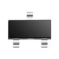
BSR56 T/R NXP Semiconductors, BSR56 T/R Datasheet - Page 2

BSR56 T/R
Manufacturer Part Number
BSR56 T/R
Description
RF JFET TAPE7 FET-RFSS
Manufacturer
NXP Semiconductors
Datasheet
1.BSR56_TR.pdf
(6 pages)
Specifications of BSR56 T/R
Configuration
Single
Mounting Style
SMD/SMT
Transistor Polarity
N-Channel
Drain Source Voltage Vds
40 V
Gate-source Breakdown Voltage
- 40 V
Maximum Drain Gate Voltage
40 V
Continuous Drain Current
50 mA
Maximum Operating Temperature
+ 150 C
Package / Case
SOT-23
Lead Free Status / RoHS Status
Lead free / RoHS Compliant
Other names
BSR56,215
Philips Semiconductors
DESCRIPTION
Symmetrical silicon n-channel
depletion type junction field-effect
transistors in a plastic microminiature
envelope intended for application in
thick and thin-film circuits. The
transistors are intended for
low-power, chopper or switching
applications in industrial service.
PINNING
Note
1. Drain and source are
Marking code
QUICK REFERENCE DATA
April 1991
1
2
3
BSR56 = M4P
BSR57 = M5P
BSR58 = M6P
Drain-source voltage
Total power dissipation up to T
Drain current
Gate-source cut-off voltage
Drain-source resistance (on) at f = 1 kHz
Feedback capacitance at f = 1 MHz
Turn-off time
N-channel FETs
V
V
I
V
I
I
I
D
D
D
D
interchangeable.
V
= drain
= source
= gate
DS
DS
DD
= 0; V
= 20 mA; V
= 10 mA; V
= 5 mA; V
GS
= 15 V; V
= 15 V; I
= 10 V; V
= 10 V; V
GS
= 0
D
GS
GS
= 0.5 nA
GSM
GSM
GSM
DS
= 0
= 0
= 0
= 10 V
= 6 V
= 4 V
amb
= 40 C
handbook, halfpage
Fig.1 Simplified outline and symbol, SOT23.
2
Top view
1
P
I
r
C
t
t
t
DSS
off
off
off
ds on
V
V
tot
rs
DS
(P)GS
3
max.
max.
2
BSR56
BSR56; BSR57; BSR58
250
40
50
10
25
25
4
5
g
MAM385
BSR57
Product specification
d
s
250
100
40
20
40
50
2
6
5
BSR58
250 mW
100 ns
0.8 V
40 V
80 mA
60
8 mA
4 V
5 pF
ns
ns


